
Variable Frequency Drives

Table of contents
- Introduction
- Classification of Drives
- Principles of Operation – AC VFD Drives
- Selection of VFD Drives
- Application considerations and estimated Savings for VFD Drives
- Case Studies
- Appendix A: Bibliography
- Appendix B: Useful Web Sites
- Appendix C: Industry Acronyms and Glossary Of Terms
- Appendix D: Useful Formulas
- Appendix E: Conversion Factors
Introduction
Scope of the Variable Frequency Drive
This guide has been developed as an overview of Variable Frequency Drive (VFD) technology to assist in the effective understanding, selection, application, and operation of VFDs. In this guide, the word “drive” refers to the electronic VFD.
This guide does NOT cover other Variable Speed Drives (VSDs) that have mechanical or hydraulic controls.
The primary focus of this guide is for ‘off-the-shelf’, low voltage VFDs used in conjunction with AC, polyphase, induction motors in the factional to 500 horsepower range that are:
- 600V or less
- IGBT PWM (pulse width modulated using insulated gate bipolar transistors)
- Commercially available
Engineered products for special and large motor applications are not included.
Selecting the proper VFD for your application is best achieved by understanding the technology, your specific load requirements and asking the right question up front. This question might be:
“Does my load profile vary sufficiently to justify a VFD?”
Note: It is strongly recommended that individuals or companies installing VFDs secure the services of a professional specialist qualified in VFDs in order to understand and maximize the available benefits.
Project managers for VFD projects who are not familiar with the technology often undervalue the importance of obtaining the correct data, analysis and up-front engineering that is necessary to thoroughly understand the system.
Overview of Variable Frequency Drives
A Variable-Frequency Drive (VFD) is a device that controls the voltage and frequency that is being supplied to a motor and therefore controls the speed of the motor and the system it is driving. By meeting the required process demands, the system efficiency is improved.
A VFD is capable of adjusting both the speed and torque of an induction motor.
A VFD therefore provides continuous range process speed control (as compared to the discrete speed control that gearboxes or multi-speed motors provide).
VFDs may be referred to by a variety of other names, such as variable speed drives, adjustable speed drives, or inverters.
Motor Speed Control
AC (Alternating Current) induction motors are essentially constant speed machines, with a variation of speed from no load to full load of about 2-5%, representing the “slip” of the motor.
The speed of the machine is determined by the frequency of the power supply and the number of magnetic poles in the design of the stator.
Fixed speed motors serve the majority of applications. In these applications or systems, control elements such as dampers and valves are used to regulate flow and pressure. These devices usually result in inefficient operation and energy loss because of their throttling action.
However, it is often desirable to have a motor operate at two or more discrete speeds, or to have fully variable speed operation. The conventional control elements can often be replaced by incorporating variable speed operation using a VFD.
Substantial energy savings can be achieved in many of these applications by varying the speed of the motors and the driven load using a commercially available VFD. Savings include capital costs and maintenance costs associated with these control elements.
The following table gives typical examples of loads and their energy savings potential.
| Type Of Load | Applications | Energy Consideration |
|---|---|---|
|
Variable Torque Load |
- Centrifugal Fans |
Lower speed operation results in significant energy savings as power to the motor drops with the cube of the speed. |
|
Constant Torque Load |
- Mixers |
Lower speed operation saves energy in direct proportion to the speed reduction. |
|
Constant Horsepower Load |
- Machine tools |
No energy savings at reduced speeds; however, energy savings can be realized by attaining the optimized cutting and machining speeds for the part being produced. |
Economics
Economics is typically one of the most important factors involved in selecting industrial equipment, but the method of evaluation is not straightforward. Many important economic considerations are often ignored in VFD evaluations.
|
Airflow Volume (percent of maximum) |
Daily Operating Time |
Energy Consumed with Damper (kWh/year) |
Energy Consumed Using a VFD (kWh/year) |
Difference |
|---|---|---|---|---|
|
50% Total |
2 24 |
18 500 251 200 |
4 800 145 100 |
13 700 106 100 |
Reference: Office of Energy Efficiency, Natural Resources Canada, “How Much Will I Save”
Electrical savings are important but there are also other factors that should be included as part of an evaluation of the life- cycle costs of the equipment. For example when pumps or fans are operated at reduced speeds there are often significant maintenance savings due to reduced wear on seals, bearings, shafts, etc. The purchase price is typically less than 10% of the life cycle costs when operating and maintenance costs are considered. Productivity increases from reduced downtimes and reduced waste from optimized process control should also be quantified for significant life cycle cost economics.
Simple Payback Evaluation
The simple payback method is frequently used to determine how long it would take for a piece of equipment to “pay for itself” through saved costs. The payback time is calculated as follows:
This method should only be used as a risk indicator. Simple payback neglects the impact of a number of important variables, such as tax incentives, inflation, etc.
The following table provides a ‘VFD checklist’ of costs and savings and can help avoid overlooking economic considerations.
| Capital Costs | Capital Savings | Operational Costs and Saving |
Other |
|
Drive |
Control valves |
Energy (total energy consumed, peak demand change) |
Salvage Value |
Net Present Value Evaluation
Calculating the net present value (NPV) is a better technique for appraising the profitability of an investment. By using the discounted cash flow technique, the NPV takes into account the time value of money. A summary of this approach appears in the following steps:
- Evaluate the cost/savings of the factors in the above table for each option that is being considered (for example, purchasing a VFD or purchasing a mechanical drive system instead). Capital costs will be expressed in total dollars; operating expenses will be expressed in terms of time.
- Determine the real discount rate that should be used for each time dependent and future-valued factor. For example, for energy savings calculations:
- x% per annum = nominal discount rate
- y% per annum = rate at which electricity rates will rise
- i% = {x/y – 1}%
- The factors for each option should be discounted to their present values, using the appropriate discount rate. The number of years used for time dependent factors should be chosen as a reasonable payback period. Present value tables and annuity tables are useful for the discounting process.
- The net present value (NPV) of each option is found by summing the costs and savings that have been calculated in present value terms for each factor.
- For any option, if:
- NPV > 0, there is a net gain
- NPV < 0, there is a net loss
- NPV = 0, breakeven occurs at the time under consideration.
- The option with the greatest positive value of NPV is the most profitable.
- The procedure could be repeated assuming different total time periods.
- A comparison between two options could also be made by using the relative difference between the options for each factor and finding one NPV.
Capital Costs
Variable Frequency Drive
The cost of Variable Frequency Drives can vary greatly, depending on the options required.
The cost should include:
- speed controls,
- start/stop controls,
- engineering,
- cable and conduit,
- foundations,
- spare parts and any related modifications.
For example, a battery back-up for the controls may be provided for auto restart or shut-down sequences.
Motor
The cost of an inverter duty motor should be considered for a new system; however, if the system is being considered for an upgrade to a VFD then the existing motor should be reviewed for size, capacity and efficiency. Usually only high efficiency motors should be considered.
See the CEATI Motor Energy Efficiency Reference Guide for more details.
Power Conditioning Equipment
The cost of any power conditioning equipment, such as harmonic filters, should be included. This includes filters for incoming power to the motor as well as power conditioners for harmonic voltages and currents sent back to the power supply from the drive.
Installation
Installation, labour and commissioning charges for the drive, motor and power conditioning apparatus should be determined.
Electrical System Upgrade
Upgrading the electrical system may be necessary if reliability greater than what the present system can offer is required. Potential upgrades include relay protective systems, supply transformer redundancy, transfer switching/alternate feeders, maintenance, emergency staff training and preventive maintenance programs.
Torsional Analysis
A torsional analysis will define the vibration effects of inverter harmonics in the drive train. This should be conducted for large drive applications.
Space Requirements
This includes the cost of any indoor space requirements for the drive and filters, as well as any outdoor space costs, such as those associated with transformers, filters or reactors.
Cooling
Additional cooling may be required for drive installation. Water cooling may be a much more economical alternative for large applications, although HVAC equipment is often used.
Capital Savings
Use of a VFD may avoid certain capital investments. Examples are gear boxes, control valves, fluid coupling/mechanical speed changing equipment and reduced voltage starters.
Operating Costs and Savings
Electrical Energy and Demand Savings
There may be savings in terms of both energy consumed (kWh) and peak demand (kW) charges. The extent of these savings depends on the specific load profile of the application, the load profile of the overall operation, the local utility’s rate schedule, etc.
Installing a VFD, in addition to the other benefits, will usually reduce the total energy consumed (kWh). Manufacturers and utilities have on-line spreadsheets that can be downloaded, typically at no cost, and used to estimate the electrical savings.
The other element of electrical power cost is the apparent power charge, measured in kVA, which compensates the utility for the peak current that must be delivered during the month. Each utility rate structure is different and contacting your utility can ensure that the correct rates are being used. The figure below illustrates the daily demand (kW) and the apparent power (kVA). The ratio between kW and kVA is the power factor. Most utilities now charge a power factor penalty, i.e., charging for apparent power (kVA) rather than kW.
.jpg)
Figure 1: Demand (kW) and Apparent Power (kVA)
Courtesy of UGS Profiler, Real time monitoring
The most significant factor affecting demand is the power required by the load. Variable frequency drives provide significant savings if the demand can be reduced.
It is also important to keep in mind the actual cost of the kilowatt-hours (kWh) of energy being saved. In the case of fixed price contracts or increasing rate blocks, the kWh saved are the last ones that would have otherwise been purchased and would usually have been charged at the highest price. However some utilities continue to use inverted and/or fixed cost rate structures so the actual cost per kWh is dependent on the utility’s rate structure.
In deregulated markets where the price per kWh varies depending on the supply and demand, each application’s energy savings will be dependant on the electric energy price for that period. For example, the volatile price in Ontario is illustrated below:
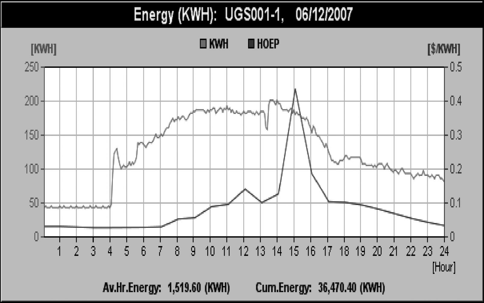
Figure 2: Electrical Energy (kWh) and Hourly Ontario Energy Price (HOEP) ($/kWh) Price - Courtesy of UGS Profiler, Real time monitoring
.jpg)
Figure 3: Resulting Electric Energy Cost for 24 hours - Courtesy of UGS Profiler, Real time monitoring
Thus it is important to properly evaluate the true benefit of energy savings since using an “average energy cost” can be misleading.
Process Flow and Operational Improvements
Often the installation of the VFD will result in operational improvements and these efficiencies should be factored into the savings.
Elimination of other Mechanical Control Devices
The installation of the VFD may eliminate some mechanical control devices including valves and dampers. The costs associated with the purchase and maintenance of these devices also needs to be included in the VFD savings evaluation.
Advantages of using VFD: Maintenance / Useful Life
The reduction of maintenance and downtime may be quite substantial if an AC variable frequency drive is employed. Contributing factors are elimination of control valves, current-limit feature (prevents motor burnouts caused by multiple restarts) and protection of the motor insulation (it will be shielded from external voltage problems).
Useful equipment life, such as for bearings, can be extended by operating at reduced speeds. Stresses and metal fatigue in the drive train shafts will be lowered.
Improvements to VFD technology and ‘off the shelf’ spares have reduced repair time significantly and have generally not resulted in an operation issues.
Over-Speed Capability
The over-speed capability of variable frequency drives can save considerable operating costs, as well as investment, if increases in production levels occur. For example, the airflow through an existing fan may be increased by retrofitting a VFD to the fan motor, which will allow operation at a frequency higher than an existing 60 Hz rating.
Considerations in applying VFDs (Tips & Cautions)
A variable frequency drive is the most cost effective choice if the duty cycle is more evenly distributed over the entire range of flow rates. Relative energy savings improve if the performance and system resistance curves are steep.
Many potentially good VFD applications are passed up because benefits other than energy savings are overlooked. Frequently, process control and reliability far outweigh efficiency related benefits to the user. By using the average cost of energy in savings analyses, the savings can be understated for variable frequency applications. Instead, both the energy and demand charges of the local utility’s rate schedule should be used.
For variable torque loads, the variable frequency drive savings can be significantly greater since the horsepower varies proportionally to the cube of the speed. For horsepower applications above 25 HP, installation costs are usually comparable to the total capital cost for the drive. Below 25 HP, installation costs may be more than the cost of the drive.
Classifications of Drives
AC Drives
Variable Frequency Drives
Electronic VFDs are speed control devices which vary the voltage and frequency to an induction motor using a technique called Pulse Width Modulation (PWM). VFDs have become the preferred way to achieve variable speed operation as they are relatively inexpensive and very reliable.
VFDs use power semiconductor devices called insulated-gate bipolar transistors (IGBT). Using PWM, the speed of the motor and torque characteristics can be adjusted to match the load requirements. They convert the fixed frequency AC supply voltage to a variable frequency, variable voltage AC supply to the motor and can regulate the speed of an induction motor from about 10% to 200% with wider ranges possible depending on the model and options selected.
The speed accuracy is affected by the slip of the motor, resulting in slightly slower operation than the synchronous speed for a given frequency. The accuracy can be increased greatly by using tachometer feedback. Extremely precise speed and position control of the motor shaft can be achieved by using a VFD with Vector Control.
The VFD can provide many solutions depending on the required application. For example, a VFD can provide the following:
- Energy savings on fan and pump applications
- Better process control and regulation
- Speeding up or slowing down a machine or process
- Inherent power-factor correction
- Bypass capability in the event of an emergency
- Protection from overload currents
- Safe acceleration.
Other AC Drives
Wound Rotor Motor Control
Wound rotor motors are a special type of induction motor with copper windings on the rotor rather than typical aluminum, squirrel cage rotor bars.
Connections to these windings are available through a slip ring assembly on the shaft.
If the windings are connected as a short circuit, the motor operates like a fixed speed squirrel cage motor, but if resistance is added to the circuit the slip of the motor increases thus allowing the speed of the motor to be adjusted.
The energy removed from the rotor circuit during the starting procedure is wasted in the resistors as heat.
As an alternative, an electronic circuit can be used instead of resistors, to reduce energy wasted. This circuit recovers the energy and feeds it back to the AC supply system, increasing the overall efficiency of the motor operation.
This motor control technique was once a popular method of speed control, but has largely being replaced by electronic VFDs.
Multi-Speed Motors
Multi-speed motors are induction motors with specially wound stators that allow the number of magnetic poles to be changed by reconnecting the windings of the motor.
Single winding multi-speed motors allow a speed ratio of 2:1. Pole changing is accomplished by reconnecting the windings which doubles the number of poles by reversing the current in each alternate coil group. This is known as consequent pole changing.
Two winding motors can be configured for any number of poles, so other speed ratios are possible. Three speeds are possible by configuring one of the two windings for consequent pole changing. Four speeds are possible by configuring each of the two windings for consequent pole changing.
Because two winding multi-speed motors have to accommodate a second set of windings, they are often larger for a given horsepower than their single speed counterparts.
Multi-speed motors are a relatively inexpensive option where fixed and limited discrete operating speeds are acceptable.
Variable Voltage Speed Controllers
These controllers typically use Silicon Controlled Rectifiers (SCRs) to control the voltage to the motor.
Under reduced voltage, a motor will “slip” more and thus its speed will be reduced.
This control scheme is generally limited to fan applications and requires a motor with high slip rotors.
The control is imprecise and has limited application to single phase Permanent Split Capacitor (PSC) motors. These are typically found in agricultural applications up to several HP.
Variable voltage speed controllers are no longer used in industrial and commercial applications.
DC Drives
Direct current (DC) motors are inherently variable speed machines. Speed and torque control is achieved by varying the armature voltage, the field excitation, or both.
Traditionally, speed control for a DC motor came from a motor-generator, or M-G set. In an M-G set, an AC motor drives a DC generator to provide variable voltage DC for motor operation. M-G sets are large, inefficient and require a lot of maintenance.
M-G sets have now been replaced with microprocessor controlled rectifier sets, which permit simple and accurate speed control, high efficiency and reliability.
However, due to the complexity, cost and maintenance associated with a DC motor, they are seldom used in new applications. Many existing DC drive applications are being replaced with AC motors and VFDs.
New applications using DC motors and drives are usually engineered applications where AC motors and drives cannot fulfill a load requirement. An example is for traction drives where the starting torque requirements exceed that available from AC motors.
Eddy Current Clutches
Eddy current clutches can be used to control standard AC squirrel-cage induction motors. However, they are low efficiency compared to VFDs and have limited applications.
An eddy current clutch has essentially three major components:
- a steel drum directly driven by an AC motor,
- a rotor with poles,
- windings on the poles that provide the variable flux required for speed control.
A voltage is applied to the pole windings to establish a flux and thus relative motion occurs between the drum and its output rotor.
By varying the applied voltage, the amount of torque transmitted is varied and therefore the speed can be varied.
Advanced Motors
Advanced motors are generally classified as a group of motor designs which require power electronics and microprocessor control for operation. This concept was formulated many years ago, but is only now practical with today’s electronics. All advanced motors allow for variable speed operation.
They are now starting to be used in original equipment manufacturer applications, for instance as blower motors in high-end heat pumps and air compressors. Some advanced motors have become available as general purpose motors with ratings up to about 600 HP. Examples include Switched Reluctance motors, Electronic Commutated motors, and Written Pole motors.
Mechanical Speed Control
Variable speed operation of machines can be achieved by using a fixed speed motor with a mechanical speed control device. Examples include fluid couplings, adjustable pulley systems, magnetic speed control, and mechanical transmissions such as belt drives, chain drives, gear boxes, etc.
Mechanical methods of speed control require the motor to operate at a constant speed and the choice of coupling alters the speed for the applied load. The efficiency of the systems is dependant on a number of factors including belt tension, type and number of belts/chains, etc. Typical mechanical methods have constant and preset speeds which cannot be dynamically adjusted to variable loads. Mechanical speed control devices typically have low efficiencies at low loads.
Principles of Operation - AC VFD Drives
AC Induction Motors
An AC induction motor is constructed with a rotor that has windings which intersect the rotating magnetic field generated by the stator windings.
At full load speed, the rotor turns slightly slower than the synchronous speed of the motor. This is because the magnetic field causes currents to flow in the rotor windings and produces a torque which turns the rotor; so if the rotor turns at the same speed as the magnetic field, there would be no relative motion between the rotor and the magnetic field, and no torque would be produced.
The amount of speed by which the rotor lags the rotating magnetic field is known as the slip of the motor. The higher the slip, the more torque is produced by the motor.
The speed at which the magnetic field rotates depends on the number of poles or coils distributed around the stator and the frequency of the supply current. This is called the synchronous speed.
Synchronous Speed = 120 x Frequency
Number of poles
Typical AC induction motor speeds are 3600, 1800, 1200, and 900 RPM.
The following diagram shows the torque-speed relationship of a typical induction motor.
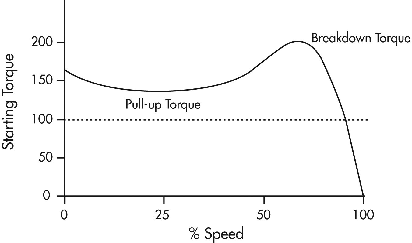
Figure 4: Torque-speed Curve of an Induction Motor.
Text version: Figure 4
Figure 4
Graph with starting torque on the vertical axis going from 0 to 200 and % speed on the horizontal axis going from 0 to 100.
Plotted line starts at 160 starting torque and 0% speed and curves downward to 125 starting torque at 25% speed where it begins to curve back upwards until it reaches at peak of 200 starting torque at 75% speed. The plotted line then drops down to 0 starting torque at 100% speed. The initial downward curve is labelled as "Pull-up Torque" and the drop off after the peak is labelled as "Breakdown Torque".
Squirrel Cage AC Induction Motors
Most AC induction motors are squirrel cage motors.
The rotor windings in a squirrel cage motor are aluminum or copper alloy bars that are positioned along the direction of the shaft and short circuited by end rings as shown in the following diagram.
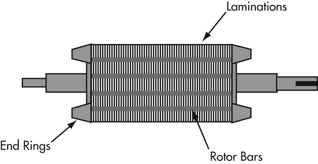
Figure 5: Diagram of a squirrel cage rotor
The shape of the bars and the resistance of the alloy used in their construction influences the torque-speed characteristics of the motor.
Pulse Width Modulated Variable Frequency Drives
When operated from a constant frequency power source (typically 60Hz), AC induction motors are fixed speed devices.
A variable frequency drive controls the speed of an AC motor by varying the frequency supplied to the motor.
The drive also regulates the output voltage in proportion to the output frequency to provide a relatively constant ratio of voltage to frequency (V/Hz), as required by the characteristics of the AC motor to produce adequate torque.
The first step in this process is to convert the AC supply voltage into DC by the use of a rectifier. DC power contains voltage ripples which are smoothed using filter capacitors. This section of the VFD is often referred to as the DC link.
This DC voltage is then converted back into AC. This conversion is typically achieved through the use of power electronic devices such as IGBT power transistors using a technique called Pulse Width Modulation (PWM). The output voltage is turned on and off at a high frequency, with the duration of on-time, or width of the pulse, controlled to approximate a sinusoidal waveform.
Older drive technologies like Current Source Inverters and Variable Voltage Controllers used SCRs or Thyristors as control devices. These technologies have now been replaced by the PWM VFD.
The entire process is controlled by a microprocessor which monitors the:
- incoming voltage supply,
- speed set-point,
- DC link voltage,
- output voltage and current to ensure operation of the motor within established parameters.
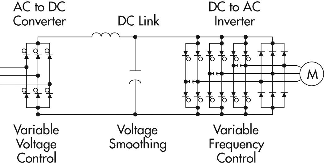
Circuit diagram for a Pulse Width Modulated Variable Frequency Drive
Graph comparing voltage to current for a Pulse Width Modulated Variable Frequency Drive
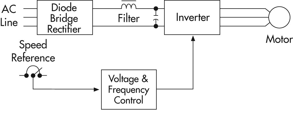
Figure 6: Block diagram of a typical PWM VFD
In the simplest drives or applications, the speed reference is simply a set-point; however, in more complex applications, the speed reference comes from a process controller such as a Programmable Logic Controller (PLC) or a tachometer.
Selection of VFD Drives
Electrical Considerations When Applying VFD to AC Motors
Successful application and maintenance of VFD drives requires an understanding of their impact on the motor and electrical distribution system.
The application of VFDs to induction motors can cause effects which must be considered for successful operation. Examples include:
- The ability of a motor to cool itself effectively is reduced as the motor is slowed down. Over-sizing the motor or providing external forced air ventilation may be required with extended operation at low speeds and high loads.
- Operation at different speeds can cause mechanical resonances in driven equipment. These speeds should be identified and programmed out of the motor’s operating range.
- VFDs generate harmonic voltages and currents which can, in some cases, cause undesirable effects on the electrical distribution system and affect equipment operation. If a power quality problem is suspected, the electrical system should be examined by a qualified person. Sometimes isolation transformers, line reactors or filtering devices will be required to minimize these effects. Contact your local electrical utility representative for more information. Installation of filtering devices should be considered at the time of purchase of VFDs to minimize power quality issues in the electrical system. A practitioner trained in this area should be used to evaluate and determine this requirement.
Electrical Supply to Drives
AC drives require an acceptable electrical supply for safe, successful and reliable operation.
Single phase drives have standardized voltages of 120 and 240 volts. Three phase motors have standardized voltages of 200, 230, 460 and 575 volts.
The nominal supply voltage of the distribution system is normally higher than the drive nameplate voltage to allow for voltage drops from the distribution transformer to the point of utilization.
Rated frequency is usually 60Hz (hertz or cycles per second) in North America.
Harmonics
Harmonic distortion of voltage and current is produced in electrical systems by non-linear loads such as VFDs, welders, rectifiers, Uninterruptible Power Supplies (UPS), arc furnaces etc. Harmonics cause electrical waveform distortion that can propagate through the entire power system and even outside of the plant. The source of harmonic distortion in VFDs is the solid-state power switching devices used to generate the varying supply frequencies.
These effects, known as “line harmonic currents”, are multiples of the fundamental 60 Hz supply current. For example, a frequency of 180 Hz is called the third harmonic. These currents generate harmonic voltage distortions which often exceed acceptable levels.
For more information, refer to the CEATI Power Quality Energy Efficiency Reference Guide.
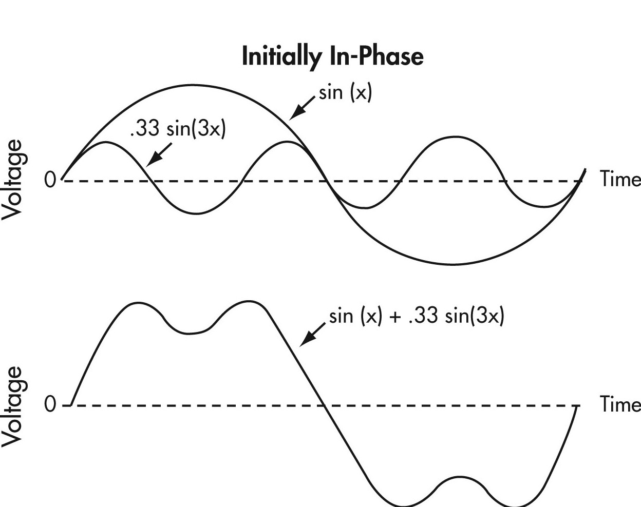
Figure 7: Harmonic Amplitudes
Text version Figure 7
Figure 7
Two graphs illustrating harmonic amplitudes. The two graphs each show two sin waves representing voltage vs. time, crossing over a middle dashed horizontal line.
In the first graph the larger sin wave is marked as sin(x) and the second sin wave is marked as .33 sin(3x). Sin wave sin(x) shows one cycle with one half of the wave above the horizontal line and one half below. Sin wave .33 sin(3x) shows three cycles in the same span as one cycle of sin wave sin(x), with three waves above the dashed line and three waves below the dashed line.
The second graph illustrates the formula sin(x) + .33 sin(3x). It shows one cycle of a double humped sin wave, with one half of the wave above the dashed line and one half below it.
The odd harmonic amplitudes usually decrease with increasing frequency, so the lowest order harmonics are the most significant. Even numbered harmonics are not normally generated by VFD drive systems.
Harmonics occur as long as the harmonic generating equipment is in operation and tend to be of a steady magnitude.
Harmonics may be greatly magnified by power factor correction capacitors. The supply system inductance can resonate with capacitors at certain harmonic frequencies developing large currents and voltages, which can damage equipment.
Effects of Harmonics
Microprocessors, numerically controlled machines, and process controllers all rely on accurate control signals. The presence of harmonics can cause these devices to malfunction. Harmonics can also cause interference with computers and improper operation of electronic equipment. They can also cause capacitor and fuse failure.
Motors run at higher temperatures in the presence of harmonic currents. Motors consume more energy as they have to overcome ‘counter rotating’ torques created by odd harmonics.
This may cause premature breakdown of insulating materials and a reduction in life. The motor will also drop in overall efficiency, experience voltage stresses on its windings and experience torque pulsations.
Dealing with Harmonics
If a harmonic problem is suspected, it should be confirmed before any attempt at corrective action is taken. A fairly simple test consists of viewing the power system waveforms on an oscilloscope. Significant waveform distortion is an indication of harmonic presence. Power harmonic analyzers can be used to measure the magnitude of the individual harmonics. This work is often best left to an expert in power quality services.
There are a variety of ways in which users can resolve these problems, after ensuring the installation meets the applicable electrical code including adequate grounding:
Separate Supply
Ideally, loads producing harmonics, and sensitive loads, should be supplied from entirely separate feeders and independent transformers.
Isolation Transformers and Line Reactors
Isolation transformers and line reactors are frequently used to protect the drive as well as the AC line from distortion.
Filters
Harmonic filters can be used to reduce the amplitude of one or more fixed frequency currents to prevent them from entering the rest of the system. Filters can be custom designed to suit the electrical environment.
Cable Length
Cable length should be kept as short as possible, i.e., less than 15 meters or 50 feet, wherever possible.
As a general rule of thumb, it is considered good practice to buy a complete drive system that includes line reactors rather than just purchasing the drive on its own. Generally a 3% to 5% impedance line reactor will prevent harmonics generated by a VFD from interfering with sensitive equipment on the distribution system.
If non-linear loads exceed 20% of the total plant load, special consideration should be given to performing a harmonic study and minimizing potential harmonic impact through the use of isolation transformers in addition to line reactors.
Specifying Drives for Harmonics
Drive specifications often cite “The power conditioning equipment shall not produce voltage distortion or notches in excess of the limits suggested in IEEE 519”, but it may be unclear what this means for a particular installation. What does meeting IEEE 519 mean when installing a drive on a power system?
IEEE’s Recommended Practices and Requirements for Harmonic Control in Electric Power Systems, IEEE Std 519-1992, is often referenced but may not be well understood.
IEEE 519-1992 contains sections on problems caused by harmonic currents and voltages, calculation examples, application examples, and the harmonic currents caused by different types of power converters and non-linear loads.
From a practical drive application point of view, meeting harmonic requirements for drives means having less than 5% total harmonic distortion of the current at the terminals of the drive at rated load. At low power demand with variable torque loads, the current’s total harmonic distortion (THD) may be higher than 5% as measured by a harmonic analyzer, but the magnitude of the harmonic current will be less than those produced at full load.
Motor Considerations
Motor Electrical Issues
Winding insulation systems are classified by their temperature or thermal capabilities. Tests used to prove thermal properties for low voltage systems do not stress the electrical insulation beyond 600 volts.
Application of a PWM VFD can cause voltage transients well above the rated voltage of the motor which can lead to failure of the insulation system in a very short period of time.
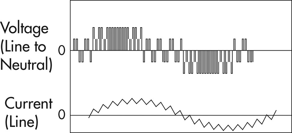
To understand this, consider the way in which a PWM inverter approximates a sinusoidal current waveform. The following figures show typical voltage and current waveforms for Pulse Width Modulation inverters.
Figure 8: Voltage and Current Waveforms
Text version Figure 8
Figure 8
Two graphs illustrating voltage and current waveforms.
The first graph shows the voltage waveform and is made up of a series of pulses controlled by the inverter’s output devices. The width or duration of these pulses is controlled to approximate a sinusoidal current waveform. Each pulse appears as bar above or below the horizontal line representing the zero voltage point.
The second graph illustrates a current waveform, which appears as a saw tooth pattern that approximates a sin wave. The saw tooth pattern goes above and below the zero voltage horizontal line for one cycle.
The voltage waveform is made up of a series of pulses controlled by the inverter’s output devices. The width or duration of these pulses is controlled to approximate a sinusoidal current waveform. Figure 9 is a half cycle voltage waveform for a typical PWM inverter operating on a 600 volt system.
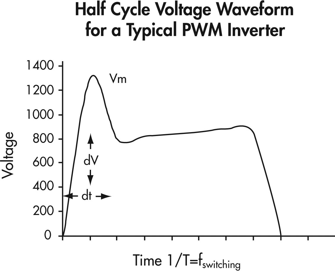
Figure 9: Half Cycle Voltage Waveform for a Typical PWM Inverter
Text version Figure 9
Figure 9
A graph showing voltage on the vertical axis and time on the horizontal axis.
The graph illustrates a half cycle voltage waveform which rises quickly in one time unit to a voltage of 1300 and drops in one time unit to a voltage of 800 and then rises more slowly to 900 in five more time units and then drops back down to zero in one more time unit.
The maximum voltage stress on the insulation system (Vm) can be significantly higher than the motor’s rated voltage and have extremely fast voltage rise times (shown in Figure 9).
Due to multiple reflections or resonance effects, the frequency can increase due to the interactions of the PWM switching frequency and waveshape, the cable length supplying the motor, and the inductance of the motor.
A voltage reflection of up to two times the applied voltage can occur due to standing waves or a “ringing effect”, and becomes more problematic with longer cable runs (typically greater than 15 m or 50 feet).
A “ringing effect” creates very high voltage stresses across the first few turns of the motor windings, and can result in interim short-circuits and ground wall insulation failure.
This problem can be minimized by using appropriate filtering, using motors with improved insulation systems (inverter duty motors) and ensuring that repaired motors have upgraded insulation systems.
Many VFDs provide for user adjustment of the switching frequency. This frequency can be adjusted over a range as broad as 500 Hz to 20 kHz. The choice of switching frequency can be significant because it defines the number of voltage overshoots occurring at the motor in a certain amount of time. Higher switching frequencies will result in higher numbers of overshoots and higher magnitudes, which will stress the motor’s insulation system. If the motor’s peak voltage rating is higher than the level of the overshoot, high switching frequency should not be a problem. If, however, the overshoot levels are higher than the peak voltage rating of the motor, the use of a lower switching frequency may reduce the overshoot levels below the peak voltage rating of the motor. However, too low a frequency may cause an audible noise from the motor which may be undesirable in some applications such as HVAC systems.
Factors to consider include:
- reducing cable runs where possible,
- using inverter output filter reactors (1%-3% impedance is typical),
- using a lower switching frequency,
- for new and repaired motors, using additional lacing on end turns, phase paper, VPI resin and pulse resistant magnet wire enamel (triple, quad or new heavy build),
- maintaining the original winding design when rewinding motors since reducing turns increases inter-turn voltage levels.
Motor Selection Issues
Thermal considerations of motor operation with a VFD should be one of the first areas of attention for successful application. As the motor speed is reduced, the amount of cooling available from the motor’s ventilation system is reduced, so motor torque must be limited at reduced speed to avoid overheating.
In addition to the reduced cooling capability, motors have additional internal heating due to the non-sinusoidal voltages and currents from the inverter operation.
The application of a VFD to a variable torque load such as a fan or centrifugal pump does not usually present problems, but constant torque or constant horsepower loads can cause motor overheating at reduced speeds because there is less air flow over the motor.
It should be noted that many applications where a DC motor has been replaced by an AC induction motor with an inverter are of the constant torque or constant horsepower class.
Figure 10 shows the allowable torque of NEMA design A&B motors due to reduced cooling from operating at reduced speeds. It can be used as a guide for de-rating motors or selecting an appropriately oversized motor.
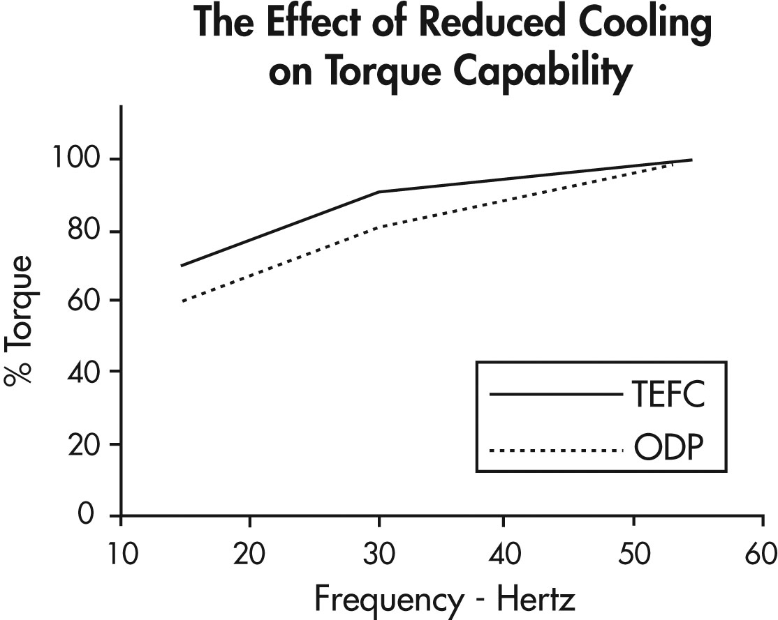
Figure 10: The Effect of Reduced Cooling on Torque Capability
Text version Figure 10
Figure 10
A graph showing per cent of torque on the vertical axis and frequency in hertz (hz) on the horizontal axis.
The graph shows two lines; a solid line marked as TEFC, and a dashed line marked as ODP.
Starting at 15 hz, the solid line is at 70% torque. It rises to 90% torque at 30 hz and then more gradually rises to 100% torque at 55 hz.
Starting at 15 hz, the dashed line is at 60% torque. It rises to 80% at 30 hz and then more gradually rises to 100% at 55 hz.
The use of a motor with a 1.15 service factor and class F insulation is generally recommended to allow for additional heating due to harmonics.
The ability of a motor to cool itself effectively is reduced as the motor is slowed down. Oversizing the motor or providing external forced air ventilation may be required with extended operation at low speeds and high loads.
“Inverter duty” motors are designed for optimized performance when operated with VFDs. These motors typically have better insulation systems and can also be forced ventilated with auxiliary blowers available as an option. This allows them to run cooler rather than having to oversize them when running high torque loads.
When applying a PWM inverter it is important to check for shaft currents on motors with frequent or unusual bearing failures. Shaft currents are not normally a problem with motors less than 20″ in core diameter, but can become a problem with high frequency harmonics associated with inverter use. Shaft voltages exceeding 0.3-0.5 volts may indicate potential trouble and may require shaft grounding or insulating the non-drive bearing.
Physical & Environmental Issues
VFDs must be selected to ensure that they have adequate protection from their environmental conditions.
VFDs are usually mounted into an electrical enclosure with other electrical devices, or as a standalone unit in its own enclosure.
The National Electrical Equipment Manufacturers Association (NEMA) has determined standard enclosure types to protect electrical equipment and to protect people from exposure to that equipment for standard environmental conditions. They are designated as follows:
| TYPE | NEMA ENCLOSURE |
|---|---|
| 1 |
General Purpose-indoor |
|
2 |
Drip proof-indoor |
|
3 |
Dust tight, Rain tight, Sleet tight-Outdoor |
|
3R |
Rain proof, Sleet Resistant-Outdoor |
|
3S |
Dust tight, Rain tight, Sleet proof-Outdoor |
|
4 |
Watertight, Dust tight, Sleet Resistant |
|
4X |
Watertight, Dust tight, Corrosion Resistant |
|
5 |
Dust tight-indoor |
|
6 |
Submersible, Water tight, Dust tight |
|
6P |
Watertight-Prolonged Submersion |
|
7 |
Class 1, Group A, B, C or D Hazardous Locations, Air-Break-Indoor |
|
8 |
Class 1, Group A, B, C or D Hazardous Locations, Oil-immersed-Indoor |
|
9 |
Class II, Group E, F, or G Hazardous Locations Air-Break-Indoor |
|
10 |
Bureau of Mines |
|
11 |
Corrosion-Resistant and Drip proof Oil-Immersed |
|
12 |
Industrial Use, Dust tight and Drip tight-Indoor |
|
12K |
Industrial Use, Dust tight and Drip tight with knockouts |
|
13 |
Oil tight and Dust tight-Indoor |
The following is a more detailed description for commonly used enclosure types:
- Type 1 — Enclosures constructed for indoor use to provide a degree of protection to personnel against access to hazardous parts and to provide a degree of protection for the equipment inside the enclosure against ingress of solid foreign objects (falling dirt).
- Type 2 — Enclosures constructed for indoor use to provide a degree of protection to personnel against access to hazardous parts, to provide a degree of protection of the equipment inside the enclosure against the ingress of solid foreign objects (falling dirt) and to provide a degree of protection with respect to harmful effects on the equipment due to the ingress of water (dripping and light splashing).
- Type 3 — Enclosures constructed for either indoor or outdoor use to provide a degree of protection to personnel against access to hazardous parts, to provide a degree of protection of the equipment inside the enclosure against ingress of solid foreign objects (falling dirt and windblown dust), to provide a degree of protection with respect to harmful effects on the equipment due to the ingress of water (rain, sleet, snow) and that will be undamaged by the external formation of ice on the enclosure.
- Type 4X — Enclosures constructed for either indoor or outdoor use to provide a degree of protection to personnel against access to hazardous parts, to provide a degree of protection of the equipment inside the enclosure against ingress of solid foreign objects (windblown dust), to provide a degree of protection with respect to harmful effects on the equipment due to the ingress of water (rain, sleet, snow, splashing water, and hose directed water), that provide an additional level of protection against corrosion and that will be undamaged by the external formation of ice on the enclosure.
In addition to protection from contamination and ingress of dirt, dust, water, etc., operation within the following limits would be considered usual operating conditions:
- Exposure to an ambient temperature in the range of 15°C to 40°C.
- Exposure to an altitude which does not exceed 3300 feet (1000 meters).
- Installation on a rigid mounting surface.
- Installation in areas or supplementary enclosures which do not seriously interfere with the ventilation of the drive.
Vibration and Resonance
There is a general assumption that slowing down rotating equipment leads to less wear and tear and hence promotes better maintenance conditions. Frequently, equipment life can be extended through the benefits of variable speed. However, there are a number of detrimental mechanical conditions that can arise when equipment is slowed down.
Most machines are designed to operate at a speed which is selected at a calculated safe margin below the first critical speed or natural frequency of the shaft.
In certain cases, to facilitate shaft design, some high speed machines are designed to operate between the first and second critical speeds. A speed reduction for a machine of this type could result in operation at the first critical speed.
For larger installations, contact should be made with the machine manufacturer to ensure that the critical speeds are known and dealt with appropriately.
Resolving vibration and resonance usually involves programming the VFD so that it will not operate equipment in the critical speed range.
If the design data cannot be located, field tests should be performed or the complete apparatus should be measured and the critical speeds recalculated.
Application considerations and estimated Savings for VFD Drives
Driven Load Characteristics and Power Requirements
The behaviour of torque and horsepower with respect to speed partially determines the requirements of the motor-drive system.
1 Horsepower (HP) = 746 Watts = 0.746 kWatts
This torque formula implies that the torque is proportional to the horsepower rating and inversely proportional to the speed.
We can categorize drive applications by their operational torque requirements:
- Constant Torque Loads
- Constant Horsepower Loads
- Variable Torque Loads where torque is the amount of turning force required by the load.
- Efficiency of Electric Motors and Drives
Constant Torque Loads
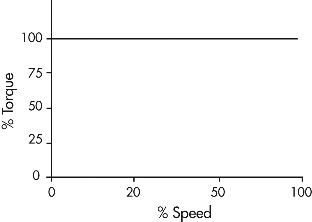
Figure 11: Constant Torque Load
Text version
Figure 11
A graph showing per cent of torque on the vertical axis and per cent of speed on the horizontal axis. There is a straight horizontal line at 100% torque representing constant torque loads from a speed range of 0 to 100%.
A constant torque load is characterized as one in which the torque is constant regardless of speed. As a result the horsepower requirement is directly proportional to the operating speed of the application and varies directly with speed. Since torque is not a function of speed, it remains constant while the horsepower and speed vary proportionately. Typical examples of constant torque applications include:
- Conveyors
- Extruders
- Mixers
- Positive displacement pumps and compressors
Some of the advantages VFDs offer in constant torque applications include precise speed control and starting and stopping with controlled acceleration/deceleration.
For constant torque loads the speed range is typically 10:1. These applications usually result in moderate energy savings at lower speeds.
Constant Horsepower Loads
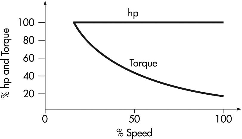
Figure 12: Constant Horsepower Load
Text version
Figure 12
A graph showing per cent of horsepower and torque on the vertical axis and per cent of speed on the horizontal axis. There is a straight horizontal line at 100% horsepower and torque representing constant horsepower loads from a speed range of 20 to 100%.
There is a second curved line representing torque beginning at 100% horsepower and torque and 20% speed and proceeding downwards to 20% horsepower and torque at 100% speed.
The second type of load characteristic is constant power. In these applications the torque requirement varies inversely with speed. As the torque increases the speed must decrease to have a constant horsepower load. The relationship can be written as:
Power = speed x torque x constant
Examples of this type of load would be a lathe or drilling and milling machines where heavy cuts are made at low speed and light cuts are made at high speed.
These applications do not offer energy savings at reduced speeds.
Variable Torque Loads
Constant Torque Loads
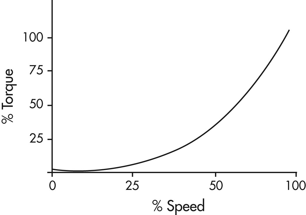
Figure 13: Variable Torque Load
Text version
Figure 13
A graph showing per cent of torque on the vertical axis and per cent of speed on the horizontal axis. There is a line curving upwards beginning at approximately 2% torque and 0% speed and ending at 100% torque and 100% speed.
The third type of load characteristic is a variable torque load. Examples include centrifugal fans, blowers and pumps. The use of a VFD with a variable torque load may return significant energy savings.
In these applications:
- Torque varies directly with speed squared
- Power varies directly with speed cubed
This means that at half speed, the horsepower required is approximately one eighth of rated maximum.
Throttling a system by using a valve or damper is an inefficient method of control because the throttling device dissipates energy which has been imparted to the fluid. A variable frequency drive simply reduces the total energy into the system when it is not needed.
- In addition to the major energy saving potential, a drive also offers the benefits of increased process control often impacting on product quality and reducing scrap.
- For variable torque loads a 3:1 speed range is typical.
Efficiencies of Motors and Drives
The full load efficiency of AC electric motors range from around 80% for the smallest motors to over 95% for motors over 100 HP. The efficiency of an electric motor drops significantly as the load is reduced below 40%. Good practice dictates that motors should be sized so that full load operation corresponds to 75% of the rated power of the motor. Figure 14 is a typical curve of motor efficiency versus loading.
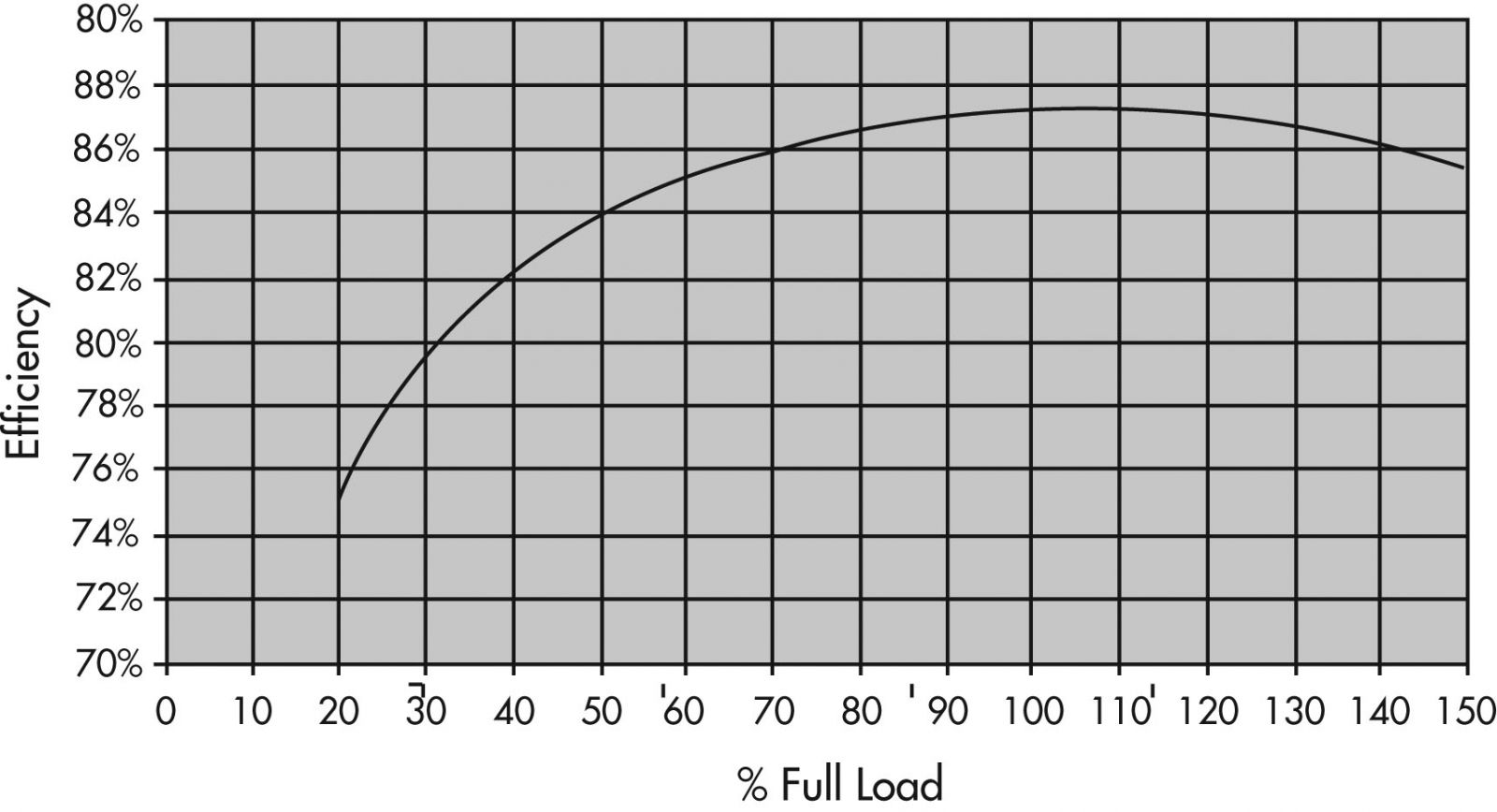
Figure 14: Typical Efficiency of a 10 HP Induction Motor Standard Efficiency Versus the Load
Text version
Figure 14
There is a second curved line representing torque beginning at 100% horsepower and torque and 20% speed and proceeding downwards to 20% horsepower and torque at 100% speed.
The efficiency of an electric motor and drive system is the ratio of mechanical output power to electrical input power and is most often expressed as a percentage.
A VFD is very efficient. Typical efficiencies of 97% or more are available at full load. At reduced loads the efficiency drops. Typically, VFDs over 10 HP have over 90% efficiency for loads greater than 25% of full load. This is the operating range of interest for practical applications.
| VFD HP rating | Efficiency % Load, Percent of Drive Rated Power Output |
||||
|---|---|---|---|---|---|
| 12.5 | 25 | 50 | 75 | 100 | |
| 1 | .48 | .74 | .84 | .87 | .89 |
| 5 | .80 | .88 | .92 | .94 | .95 |
| 10 | .83 | .90 | .94 | .95 | .96 |
| 25 | .88 | .93 | .95 | .96 | .97 |
| 50 | .86 | .92 | .95 | .96 | .96 |
| 75 | .86 | .94 | .97 | .97 | .97 |
| 100 | .89 | .94 | .96 | .96 | .97 |
| 200 | .91 | .95 | .96 | .97 | .97 |
Table from the U.S. Department of Energy’s Industrial Technologies Program – Motor Tip Sheet No. 12: Use Adjustable Speed Drive Part-Load Efficiency When Determining Energy Saving (2005 draft version).
The following table shows the efficiency of typical VFDs at various loads.
The system efficiency is lower than the product of motor efficiency and VFD efficiency because the motor efficiency varies with load and because of the effects of harmonics on the motor.
Unfortunately, it is nearly impossible to know what the motor/ drive system efficiency will be, but because the power input to a variable torque system drops so remarkably with speed, an estimate of the system efficiencies is really all that is needed.
When calculating the energy consumption of a motor drive system, estimated system efficiency in the range of 80-90 % can be used with motors ranging from 10 HP and larger and loads of 25% and greater.
In general, lower efficiency ranges correspond to small motor sizes and loads and higher efficiency ranges corresponds to larger motors and loads.
Comparison with Conventional Control Methods
Estimating Energy Savings
Fans and pumps are designed to be capable of meeting the maximum demand of the system in which they are installed.
However, quite often the actual demand could vary and be much less than the designed capacity. These conditions are accommodated by adding outlet dampers to fans or throttling valves to pumps.
These are effective and simple controls, but severely affect the efficiency of the system.
Using a VFD to control the fan or pump is a more efficient means of flow control than simple valves or inlet or outlet dampers. The power input to fans and pumps varies with the cube of the speed, so even seemingly small changes in speed can greatly impact the power required by the load. The table below shows the power required by a fan or pump as the speed of the machine is reduced.
| Speed of Fan/Pump | Mechanical Power Required |
|---|---|
| 100% | 100% |
| 90% | 73% |
| 75% | 42% |
| 50% | 13% |
In addition to major energy savings potential, a drive also offers built-in power factor correction, better process control and motor protection.
The most common application is the centrifugal fan or pump that imparts energy in to the working fluid by centrifugal force. This results in an increase in pressure and produces air flow at the outlet of the fan or liquid flow from a pump.
Figure 15 is an example of what a typical centrifugal fan can produce at its outlet at a given speed.
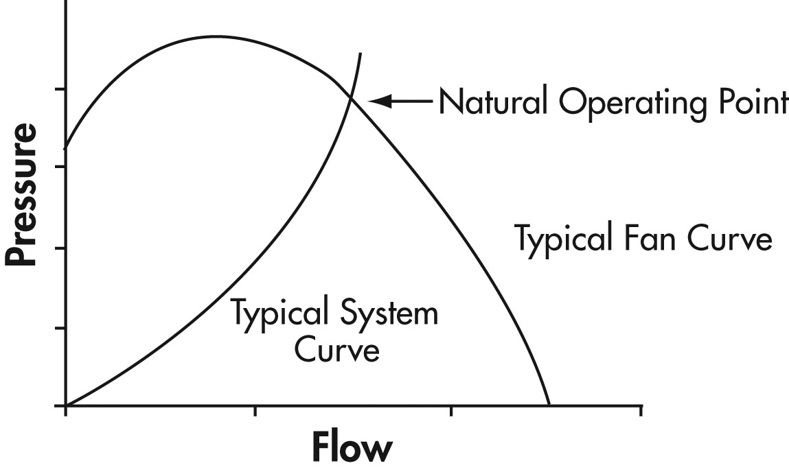
Figure 15: Plot of Outlet Pressure Versus the Flow of Air
Standard fan and pump curves will usually show a number of curves for different speeds, efficiencies and power requirements. These are all useful for selecting the optimum fan or pump for any application. They also are needed to predict operation and other parameters when the operation is changed.
Figure 15 also shows a system curve added to the fan curve. The system curve is not a product of the fan, but a curve showing the requirements of the system that the fan is used on.
It shows how much pressure is required from the fan to overcome system losses and produce an air flow.
The fan curve is a plot of fan capability independent of a system. The system curve is a plot of "load" requirement independent of the fan. The intersection of these two curves is the natural operating point. It is the actual pressure and flow that will occur at the fan outlet when this system is operated. Without external influences, the fan will operate only at this point.
Many systems however require operation at a wide variety of points. Figure 16 illustrates a profile of the typical variations in flow experienced in a typical system. How these variations are produced and controlled will have a direct effect on the energy saved.
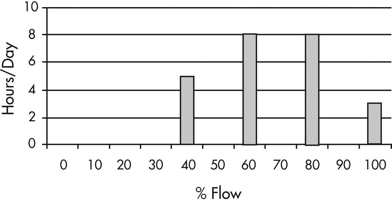
Figure 16: Variations in Flow
Text version
Figure 16
A bar chart with hours per day from 0 to 10 on the vertical axis and per cent of flow from 0 to 100 on the horizontal axis.
There are several methods used to modulate or vary the flow of a system to achieve the optimum points. Some of these include:
- Outlet dampers on fans and valves on pumps
- Inlet dampers or guide vanes on fans
- VFD control
Each of these methods affects either the system curve or the fan curve to produce a different natural operating point. In so doing, they also may change the fanâ€TMs efficiency and the power requirements.
Outlet Dampers and Valve Throttle Positions
The outlet dampers on a fan system and valves on a pump system affect the system curve by increasing the resistance to flow through their throttling action.
The system curve is a simple function that can be stated as P = K x (Flow)2. P is the pressure required to produce a given flow in the system. K is a function of the system and represents the friction to air flow. The outlet vanes affect the K portion of the formula.
Figure 17 shows several different system curves indicating different throttle positions.
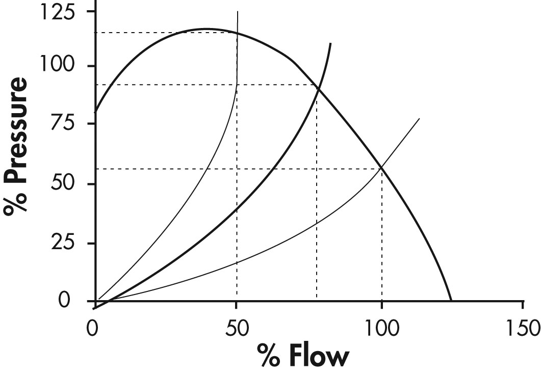
Figure 17: Pressure Versus Flow
Figure 18 presents a curve of the power requirement for this type of operation. From this curve, it can be seen that the power decreases gradually as the flow is decreased. At 50% flow 80% power is required.
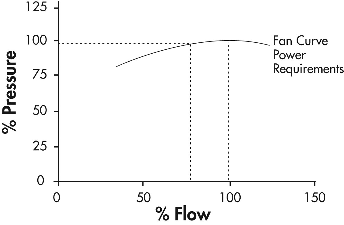
Figure 18: Pressure Versus Flow
Variable Inlet Vanes
This method modifies the fan curve so that it intersects the system curve at a different point.
There is no equivalent on a pumping system as throttling valves are never placed on the suction side of a pump.
Figure 19 illustrates several different system curves indicating different throttle positions.
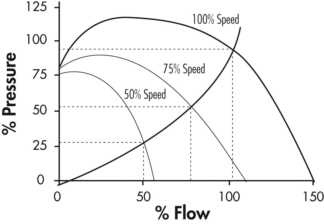
Figure 19: Fan Versus Inlet Vane Setting
Figure 20 shows that the power required by this method drops and to a greater extent than it did in the outlet throttle method. At 50% flow 60% power is required.
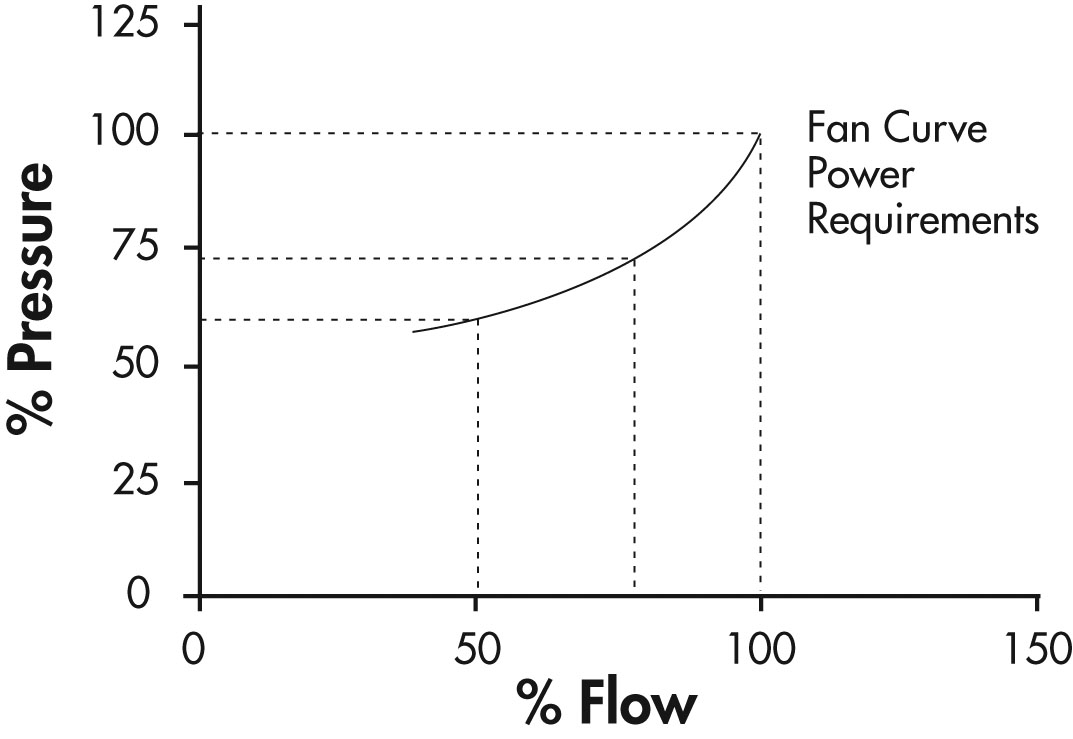
Figure 20: Fan and Inlet Vane Settings Curve
Variable Frequency Drives
This method takes advantage of the change in the fan or pump curve that occurs when the speed of the machine is changed.
These changes are quantified in a set of formulas called the affinity laws. These laws are as follows:
Where:
N = Speed
Q = Flow
P = Pressure
HP = Power
Note: when the flow and pressure laws are combined, the result is a formula that matches the system curve formula:
SYSTEM Pressure CURVE P = K x (N)².
Thus the machine will follow the system curve when its speed is changed.
Figure 21 is a representation of the adjustable-speed method.
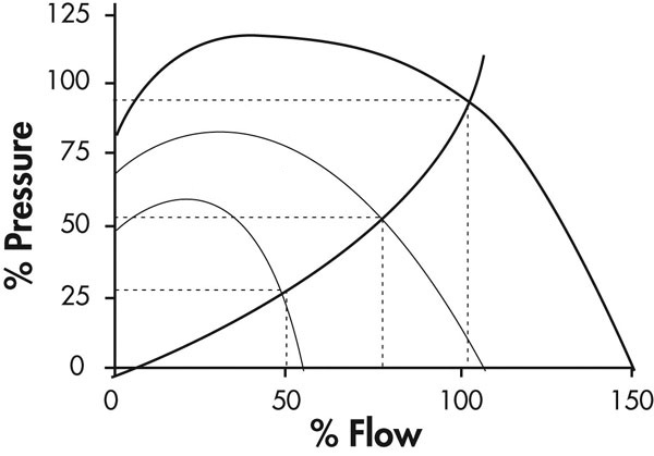
Figure 21: Adjustable-Speed Method
Figure 22 illustrates the significant reduction in power achieved by this method. The theoretical power formula from the affinity laws shows the effect of the cube functions.
Experience has shown that the actual power requirement will approximate a square function due to real life system effects like static back pressure or head, and friction so the affinity law for most real life applications is:
Where:
N = Speed
Q = Flow
P = Pressure
HP = Power
For most applications that a user will consider, the square law approximation should be used. Only fans with little or no static pressure, such as cooling tower fans and roof vent fans with domes, or pumps with no static head like discharge pumps will approximate a cube function.
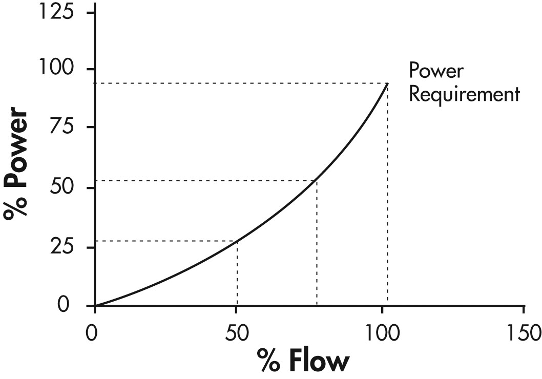
Figure 22: Square Law Approximation
Text version
Figure 22
A graph with per cent power from 0 to 125 on the vertical axis and per cent of flow from 0 to 150 on the horizontal axis.
A curve rises on the graph from 0% power and 0% flow and rises to 25% power at 50% flow, then continues to 50% power at 75% flow, and then terminates at 95% power at 100% flow.
The adjustable-speed method achieves flow control in a way that closely matches system or load curve. At 50% flow only 25% of the power is required.
This allows the fan or pump to produce the desired results with the minimum of input power.
The other two methods modify some system parameter which generally results in a reduction of the machine’s efficiency. This is why the power demand is greater than the adjustable-speed method.
Calculation of Energy Savings
It is now appropriate to estimate the power consumption and then compare the power consumption for each of the various methods to determine potential savings.
The fan selected for this example is a unit operating at 300 RPM producing a 100 percent flow rating of 2,500 m³/min, with a motor shaft power requirement of 25 kW. Pumps would be dealt with in a similar manner using the appropriate pump curve.
The fan will operate 8,000 hours per year. With no control available and at an energy cost of $0.10/kWh, the annual electricity cost will be:
(25 kW) (8,000 hrs) ($0.10/kWhr) = $20,000 /year
To determine the potential savings from a control method, a load profile must be developed. For this example, the following load profile is determined:
| Flow | Duty Cycle |
|---|---|
| 100% | 20% |
| 75% | 40% |
| 50% | 40% |
Required Power
For each operating point, a required power from the fan curve can be obtained (from the preceding curves for each control scheme).
This power is multiplied by the percent of time that the fan operates at this point. These calculations are then summed to produce a “weighted power” that represents the average energy consumption of the fan.
From the outlet damper curve (Figure 18), the weighted power calculations for the outlet damper method are as follows:
| % Flow | % Duty Cycle | Power Required (kW) | Weighted Power (kW) |
|---|---|---|---|
| 100 | 20 | 25 (1.00) = 25.0 | 25.0 (0.2) = 5.0 |
| 75 | 40 | 25 (0.96) = 24.0 | 24.0 (0.4) = 9.6 |
| 50 | 40 | 25 (0.88) = 22.0 | 22.0 (0.4) = 8.8 |
| Average Annual Power | 23.4 kW | ||
The weighted power calculations for the variable inlet vane (Figure 20) method are as follows:
| % Flow | % Duty Cycle | Power Required (kW) | Weighted Power (kW) |
|---|---|---|---|
| 100 | 20 | 25 (1.00) = 25.0 | 25.0 (0.2) = 5.0 |
| 75 | 40 | 25 (0.73) = 18.3 | 18.3 (0.4) = 9.6 |
| 50 | 40 | 25 (0.60) = 15.0 | 15.0 (0.4) = 6.0 |
| Average Annual Power | 20.6 kW | ||
The weighted power calculations for the VFD (Figure 22) method are as follows:
| % Flow | % Duty Cycle | Power Required (kW) | Weighted Power (kW) |
|---|---|---|---|
| 100 | 20 | 25 (1.00) = 25.0 | 25.0 (0.2) = 5.0 |
| 75 | 40 | 25 (0.55) = 13.8 | 18.3 (0.4) = 5.5 |
| 50 | 40 | 25 (0.25) = 6.3 | 15.0 (0.4) = 2.5 |
| Average Annual Power | 13.0 kW | ||
The annual cost of operation for the three control methods are as follows:
Outlet Dampers : 23.4 kW x $0.10/kWhr x 8000 Hours x $18,720
Inlet Dampers : 20.6 kW x $0.10/kWhr x 8000 Hours x $16,480
VFD Control : 13.0 kW x $0.10/kWhr x 8000 Hours x $10,400
The savings from these control methods are as follows:
| Control Type | Annual Operating Cost | Annual Savings |
|---|---|---|
| None | $20,000 | 0 |
| Outlet Dampers | $18,720 | $1,280 |
| Inlet Dampers | $16,480 | $3,520 |
| VFD Control | $10,400 | $9,600 |
The above calculations use a simple “blended” cost for electricity. How your utility charges for electricity usually depends on a number of factors including demand, energy, time of use and other factors. Your local utility representative should be contacted for more detail on how to calculate your electricity cost.
VFD Savings Software
Software is available from several VFD manufacturers, suppliers and in some cases local utilities along with government organizations.
These resources are very useful for estimating energy savings and exploring control options. Several will allow performance data to be input when it is available to make the analysis even more accurate.
Each source of software assumes a basic understanding of VFD technology and a thorough understanding of the application.
Monitoring and Verification
It is important to establish a Measurement and Verification plan (M&V) ahead of the project execution for several reasons, including:
- Proving the estimated savings is achieved.
- Meeting conservation and demand management incentive application requirements.
- Obtaining support for future projects through demonstrating success.
Energy savings are determined by comparing the energy use before the project starts (base case) and then again after the installation of the energy conservation measures (post project).
Proper determination of savings includes adjusting for changes that affect energy use but that are not caused by the conservation measures. Adjustments will vary on the application and include considerations such as weather, product or occupancy conditions between the baseline and post installation periods.
M&V activities generally take place in the following steps:
- Define the pre-installation baseline, including:
- equipment and systems
- baseline energy use (and cost)
- factors that influence baseline energy use.
- Define the post-project installation situation, including:
- equipment and systems
- post-installation energy use (and cost)
- factors that influence post installation energy use.
- Site surveys, spot, short-term, or long-term metering, and/or analysis of billing data can be used for the post-installation assessment.
- Conduct ongoing M&V activities to verify the operation of the installed equipment/systems, determine current year savings, and estimate savings for subsequent years.
Note: Adding a VFD is often part of an equipment upgrade.
This can affect process flow or related operations. It is important that the post project energy use is equally adjusted to match the pre-installation operating conditions.
Measurement and verification can be a fairly complex process and the success of the current VFD project or future energy efficiency projects may depend upon an accurate and detailed measurement and verification process. It must be included as part of the project costs. It is recommended that a professional practitioner be used to ensure that the measurements are done correctly. Usually the costs associated with the M & V can be recovered from available incentives.
The CEATI Energy Savings Measurement Guide provides details on the process for undertaking measurement and verification of the project.
System Efficiency
System efficiency is defined as the ratio of the units of product produced by that system to the electrical energy drawn by a system. To determine any difference, subtract the old system efficiency from the new.
If the number is negative, then the system efficiency has declined since the system optimization. The outcome should always be positive.
Electrical Efficiency
The electrical efficiency improvement is determined by comparing the base case measured electrical consumption with the electrical use determined during the project evaluation metering.
Efficiency Improvement = Post Project Efficiency – Base Case Efficiency
Cost Per Unit Product
This calculation incorporates billing data to give a dollar value to the optimization. Using the formula presented in the base case, apply the post-project metering data.
[Demand Charge for Motor + (OP kWh * OP Rate + FP kWh x FP Rate)]
Divided by:
# of Units Produced per Day
OP Rate = the rate per kWh of on-peak energy consumption
FP Rate = the rate per kWh off off-peak energy consumption
To compare against the base case, subtract the base case number from the post-optimization number. If the resulting number is negative, then the cost per unit product has increased. The number should always be positive.
Reliability and Maintenance
Solid-state electronics in VFDs are relatively maintenance free.
Most drive manufacturers supply built-in diagnostics as well as protection relays and fuses.
When service is required, trained personnel are needed to troubleshoot and repair the drive.
Routine maintenance may include cleaning/replacing filters where fitted in addition to standard electrical maintenance activities such as cleaning and inspection on a regular basis.
When repairing electric motors being operated by VFDs, the repair shop should utilize "inverter duty" magnet wire in any rewinds. In addition, they should not reduce the number of turns in coil groups as this increases the electrical stress per turn in the winding.
If the motor failed due to overheating, consideration should be given as to whether sufficient cooling is available to the motor. Fitting an external cooling fan or over-sizing the motor are two options that may be considered.
Your drive supplier or motor repair shop will be able to provide assistance for any service problems.
Case Studies
Case Study: Replacement of Eddy-Current Drive with a VFD
Company Background
The company is a 100,000 square foot plant that produces approximately 1 million linear feet of stainless steel tubing per month for its customers in the automotive, food, pharmaceutical and petrochemical industries.
Project Overview
The production process consists of drawing stainless steel tubing through dies to reduce their diameter and/or wall thickness. This drawing process is carried out on a drawbench.
Each tube typically goes through several breaking draws which rapidly form the tube close to its final dimensions. Next, the tube undergoes a few final “finishing” draws to achieve the exact tube size. The drawbench used for breaking draws operates 24/5, performing approximately 1,200 draws per day.
The breaking drawbench was powered by a 150 HP motor running at 1,800 rpm. This motor was coupled to a speed reducer through an eddy current clutch which is known to be an inefficient although reliable technology.
Approach
The implementation team used data collected by the plant engineering department to analyze the existing system. This included observing the operation of other equipment similar to the breaking drawbench and noting where similar operating parameters could be applied to the breaking drawbench.
Due to the wide variety of tube diameters, wall thickness, material used and orders received each week, a single representative product does not exist. To obtain data representative of actual operation, the project team randomly selected orders and then performed a detailed analysis of the intermediate steps to which the tubing undergoes. The team compared the power requirement that plant engineering measured in the base case study against the measured system power requirements.
Project Implementation
A VFD using vector drive options was selected as it can continuously monitor the current, voltage and angular position of the AC induction motors. Prior to the development of vector drive controls, only DC motors, which are less reliable and required more maintenance than their AC counterparts, could be used in applications requiring accurate torque and speed control. Today, vector drive options are a regular feature of VFDs.
In order to accomplish the project goals, the team replaced the magnetic starter and eddy current clutch with a VFD vector drive and line reactor. A line reactor was included as a system specification to avoid and harmonic issues on the distribution system. The plant engineer also wanted to increase the torque output to the drawbench, improve overall drive efficiency, and reduce energy consumption, so the standard efficiency 150 HP, 1,800 rpm motor was replaced with a high efficiency 200 HP, 1,200 rpm motor. The lower speed motor was chosen as it produces greater torque than the higher speed motor.
Results
As a result of the changes implemented by the team, the breaking drawbench now requires less energy to draw a tube, even though the motor size was increased from 150 HP to . For a typical draw, the eddy current coupling system required 190 HP to draw a tube, while the more efficient VFD drive requires less than 90 HP. The projected total annual operating time was also reduced by 623 hours as a result of the modifications, since the greater horsepower available enabled many of the tubes to be reduced to the desired size with a smaller number of draws.
The modifications reduced the breaking drawing bench’s total annual energy consumption from 439,065 kWh to 290,218 kWh and reduced the total annual electricity costs by 34 percent from the base case cost of $20,812.
An estimated 2,762 hours of labor per year will be saved as the result of these changes. Personnel estimate that one draw was eliminated from 1/2 of the orders processed. Time is not only saved through the reduced number of draws required to “break” a tube, but is also saved other operations required by the drawing process, such as degreasing, cut-off, swaging, and annealing. Assuming a labour rate of $8.50 per hour, the labour reduction amounts to labour cost savings of $23,473 per year. The reduced number of draws necessary also saved an estimated $41,322 of stainless steel, as fewer draws equate to fewer swaged ends cut off (waste) after each draw. Including other direct savings of $5,415, the total cost savings is $77,266. When measured against the project’s $34,000 cost, the simple payback came in at about 6 months.
| Project Implementation Costs | $34,000 |
|---|---|
| Annual Energy Cost Savings | $7,056 |
| Annual non-energy cost savings (labour & scrap) | $70,210 |
| Simple Payback (years) | 1/2 |
| Demand Savings (kW) | 189 |
| Annual Energy Savings (kWh) | 148,847 |
Case Study: Replacement of Damper Controls with VFDs in an HVAC System
Company Background
A small textile processing plant processing raw fiber wanted to improve the HVAC system performance in its plant. The company worked with a VFD specialist to retrofit 15 of the system’s fan motors with variable frequency drives (VFDs). As the plant operated 24/7, savings on the HVAC system could be cost efficient and provide better space conditioning and air quality for its workers.
Project Overview
The ventilation system uses nine supply fans and nine return fans to control and maintain proper ambient conditions, cool process machinery and provide proper air quality to its workers. Initially, a mixture of return air and fresh air is cleaned, cooled and humidity adjusted by four air washers. This air is then supplied to the facility by the nine supply fans and distributed to the plant through ceiling mounted ducts and diffusers. Nine return fans pull air through the processing area into a network of ducts. Any suspended particulate is filtered out at the inlet of each return fan.
Factors that influence the pressure, volume or resistance of the system directly impact the fan power requirements. Therefore, air density, changes to damper positions, system pressure and air filter pressure drops, supply and return air system interaction and parallel fan operation all affect how much power the fans require and must be monitored to ensure the efficient functioning of the system. Variable inlet guide vanes and outlet dampers initially controlled the system’s air flow, but were highly inefficient. Setting these devices was imprecise and resetting them could only be done manually.
Approach
To determine how to improve ventilation system performance, the company and VFD specialist collected base case system data over two weeks to measure the performance of the existing system. Motor power was electronically logged, damper positions were manually recorded based on visual inspection of the damper linkages and power was measured on each fan at ten minute intervals. These data were analyzed and the team then developed a load duty cycle to calculate energy demand, operating hours (peak, and off-peak periods) and annual energy consumption during this period for both the return fans and supply fans. This data was later compared to the new system data, collected from after installation.
Project Implementation
After determining that the ventilation system’s fans were significantly oversized, the team retrofitted 15 of the 18 fans with VFDs. The remaining fans always ran at full flow and did not need VFDs. A power and energy measurement was connected to each of the VFDs to gather load data for the new system. The system logged each fan’s speed and power consumption in 15 minute intervals and savings analysis reports were generated. With the VFDs installed, damper control was no longer necessary so the fan control dampers were left fully opened.
Results
Installation of the VFDs reduced the ventilation system’s total electricity demand from approximately 322 kW to 133 kW, a 59 percent reduction. The total annual energy consumption for the fans similarly fell 59 percent from approximately 2,700,000 kWh to 1,100,000 kWh. The energy efficiency gains were possible because the VFDs enabled plant personnel to fully open the fan control dampers and reduced fan speed. This resulted in a large drop in power consumption and allowed the system to operate more efficiently. These electricity savings translated to annual energy cost savings of about $101,000. The cost of the project was $130,000 and included:
- Cost of the feasibility study
- Capital cost
- Installation cost
- Engineering
- M&V activities
| Project Implementation Costs | $130,000 |
|---|---|
| Annual Energy Cost Savings | $101,000 |
| Simple Payback (years) | 1.3 |
| Demand Savings (kW) | 189 |
| Annual Energy Savings (kWh) | 1,579,400 |
Case Study: Replacement of Vacuum Pump Controls with a VFD in a Dairy Facility
Company Background
A dairy farm uses a vacuum system to operate automatic milking equipment that milks cows and sends the milk to a holding tank. Prior to undertaking the project, the dairy vacuum system was utilizing a vacuum pump with a 30 HP motor that controlled vacuum levels by bleeding in air from the atmosphere, which is standard practice in the industry.
Project Overview
Modern dairy milking systems used in dairy farms utilize a vacuum for automatically milking the animals. In typical dairy vacuum milking systems, several milking units are attached to the animals with teat cups and a vacuum is introduced into the milking lines by a vacuum pump which draws milk from the teats into a storage tank.
The vacuum pump is driven by a constant speed AC motor. To maintain the stable vacuum needed for milking cows, air must be removed from the system at the same rate at which it leaks into the system. Air typically enters the system through pulsators, leaks and units becoming detached from animals.
Conventional vacuum control is accomplished by running a constant speed vacuum pump sized to the largest possible airflow and allowing air to bleed into the system through a pressure regulating system.
With some technical assistance from their utility, the farm examined their vacuum pumping system to determine whether it was operating efficiently. The evaluation determined that the system’s motor was oversized for the required vacuum and the farm could lower its energy costs with a smaller, more efficient system.
Project Implementation
Using the recommendations provided, the farm decided to implement a system which reduced the motor size and operated with a VFD. The motor was replaced with a new, energy efficient 20 HP motor. In addition, the farm installed a VFD on the new motor to adjust the pumping system speed based on the system load. The dairy could have installed a larger VFD on the existing 30 HP motor, but that would have increased the capital cost and missed the opportunity for a more efficient motor.
Project Results
The implementation of the new vacuum pump system resulted in energy savings and more efficient production for the farm. While the original system drew 16 kW, the new system never uses more than 4.5 kW, even during peak needs. The farm was able to decrease the horsepower required by the vacuum system by 30% of the system’s total capacity without any decrease in vacuum pressure or system capacity. In addition, the VFD was able to change the pump’s speed to more precisely match the process vacuum requirements.
The project’s implementation has allowed the farm to achieve annual energy savings of $5,520 and 55,000 kWh, representing over 70% of the electricity used by that system. With a total cost of $8,200 the simple payback was only 1.5 years. The project also reduced maintenance costs and will lead to increased equipment life.
| Project Implementation Costs | $8,200 |
|---|---|
| Annual Energy Cost Savings | $5,520 |
| Simple Payback (years) | 1.5 |
| Demand Savings (kW) | 11.5 |
| Annual Energy Savings (kWh) | 55,000 |
Appendix A: Bibliography
Canadian Electrical Code, Canadian Standards Association
CSA C390 Energy Efficient Test Methods for Three Phase Induction Motors, Canadian Standards Association
EASA Technical Manual, Electrical Apparatus Service Association, St. Louis
IEEE 519 Recommended Practices and Requirements for Harmonic Control in Electrical Power Systems, Institute of Electrical and Electronic Engineers, New York
IEEE Standard 112 Test Procedure for Polyphase Induction Motors and Generators, Institute of Electrical and Electronic Engineers, New York
NEMA Standard MG1, Motors and Generators, National Electrical Manufacturers Association, Washington DC
NEMA Standard MG10, Energy Management Guide for Selection and Use of Polyphase Motors, National Electrical Manufacturers Association, Washington DC
Variable Frequency Drives Application Guide, Electric Power Research Institute, Palo Alto California
Robert S Carrow: Electrician’s Technical Reference: Variable Frequency Drives, Delmar Thomson Learning ISBN07668 1923 X
Appendix B: Useful Web Sites
www.energyefficiency.org
The Canadian Energy Efficiency Centre was created by the Canadian Energy Efficiency Alliance to help facilitate and ease access to energy efficiency information and resources. The Alliance promotes and advances energy efficiency and its related benefits to the economy and the environment.
www1.eere.energy.gov/industry/
The Industrial Technologies Program works with U.S. industry to improve industrial energy efficiency and environmental performance.
www.ieee.org
A non-profit organization, IEEE is the world’s leading professional association for the advancement of technology.
www.nema.org
NEMA is the trade association of choice for the electrical manufacturing industry, and is the largest trade association for manufacturers of electrical products in the United States.
http://www.eemac.ca/home/
The Electrical Equipment Manufacturers Association of Canada (EEMAC) is the meeting place for over 80 companies involved in the manufacturing and sale of electrical products, systems, and components in Canada. EEMAC focuses on the economic well-being of the industry.
http://www.midamericanenergy.com/pdf/ee_VFD_manuf.pdf
Utility Case Studies, such as this one offers further examples as the VFD installed in a rubber manufacturing plant.
http://www.Energy-Efficiency.com
Presentations and useful references are available that support the triple bottom line that energy efficiency provides, i.e.:
- Economic Prosperity
- Environmental Performance
- Social Responsibility
http://www.nrcan.gc.ca/energy/products/categories/commercial/motors/14814
Natural Resources Canada’s Office of Energy Efficiency offers online help such as:
- Description
- Estimated Savings
- Purchasing Tips
- Other useful links including manufacturing.
http://www.nrcan.gc.ca/energy/products/categories/commercial/motors/14814
Fact sheets such as the above provide additional support.
http://www.pumpsystemsmatter.org
There are many more resources, such as the Hydraulic Institute which is a market transformation initiative created to assist North American pump system users gain a more competitive business advantage through strategic, broad-based energy management and pump system performance optimization. A primary objective of the initiative is to change the decision-making process for the purchase of pumping systems and additional resources, such as the VFD is available.
Appendix C: Industry Acronyms and Glossary of Terms
Industry Acronyms
AC = alternating current
ANSI = American National Standards Institute
ASD = adjustable speed drive
BHP = brakehorsepower
CFM = cubic feet per minute
CSA = Canadian Standards Association
CSI = current source inverter
DC = direct current
DSP = digital signal processor
ECC = eddy current coupling
FPM = feet per minute
GPM = gallon per minute
GTO = gate turnoff (thyristor)
HDF = harmonic distortion factor
IGBT = insulated gate bi-thermal thyristor
IEEE = Institute of Electrical and Electronics Engineers
LCI = load-commutated inverter
NEMA = National Electrical Manufacturers Association
NPV = net present value
PAM = pulse amplitude modulation
PLC = programmable logic controller
PWM = pulse width modulated (inverter)
SCR = silicon-controlled rectifier
SR = switched reluctance
THD = total harmonic distortion
V = voltage
VSI = variable source inverter
VVI = variable voltage inverter
Glossary of Terms
Alternating Current: The flow of electricity which changes direction on a regular continuous cycle reaching a maximum in one direction, decreasing to zero, then reversing to reach a maximum in the opposite direction.
Air Gap: The space between the rotating and stationary part of an electric motor. Magnetic energy is transferred across this gap.
Ambient: The air which surrounds a motor for air cooled machines.
Ampere: A unit of current which is a measure of the rate of electron flow. It is often abbreviated as Amp. The unit of current flow is the amp.
Breakdown Torque: The maximum torque that a motor can develop at rated voltage without stalling or an abrupt drop in speed.
Brush: A current carrying material which is in contact with an armature or slip ring assembly to provide an electrical connection between rotating and stationary components of a motor.
Capacitor: A device which can store electrical charge. In an AC circuit, a capacitor causes the voltage to lead the current. The unit of capacitance is the Farad.
Commutator: An assembly which is mounted on the shaft of a DC motor to provide the switching functions between the armature coils and the power supply.
Conductor: Any material which offers little resistance to the flow of electricity such as copper.
Duty Cycle: The relationship between the operating time and the resting time of an electric motor.
Eddy Current: Localized currents in electrical steels that are caused by alternating magnetic flux resulting in losses and heating.
Efficiency: The ratio of mechanical output to the electrical input power of a motor.
Electromotive Force (emf): A synonym for voltage usually used to describe induced or generated voltages in an electric circuit.
Field: The term used to describe the stationary part of a DC machine. The field provides the magnetic flux which interacts with the armature.
Flux: The magnetic field which is established around a current carrying conductor or a permanent magnet.
Frequency: The rate at which alternating current reverses its direction of flow. The unit of frequency is either Hertz or cycles per second.
Full Load Current: The current that a motor draws at rated voltage, frequency and load.
Full Load Slip: The difference between the synchronous speed of a motor and full load speed. It is often expressed as a ratio of the synchronous speed to full load speed in percent.
Full Load Speed: The speed of the motor at rated voltage, frequency and load.
Full Load Torque: The torque that is necessary to produce rated horsepower at full load speed.
Horsepower: A measurement of power used to rate electric motors. The unit of power rating in motors is either horsepower or kilowatts. One horsepower is equal to 746 watts.
Impedance: The total opposition a circuit offers to the flow of alternating current. It is the vector sum of resistance and reactance.
Inductance: The property of an electrical circuit which opposes a change in current due to the magnetic field induced by that current.
Inertia: Inertia is the resistance an object has to a change in its state of motion. It is determined by the weight of the object multiplied by the square of the radius of gyration (k). Rotating parts do not operate at the same speed, therefore calculating the inertia for each moving part allows rotating parts to be considered as a single unit working together.
Line Voltage: The voltage supplied to the input terminals of an electric device.
Magnetomotive Force (mmf): The magnetic energy supplied in the establishment of magnetic flux. It is analogous to the electromotive force in an electric circuit.
Phase: A term used to describe the spatial relationship of windings in an electric motor or voltages and currents in an electric circuit.
Power Factor: A measurement of the difference in phase between voltage and current in an electric circuit. Most electrical devices cause the current to lag the voltage because of inductance. The voltage leads the current in capacitive circuits.
Reactance (inductive): The property of a magnetic circuit which causes the voltage to lag the current.
Resistance: The property of an electrical conductor which impedes the flow of electricity. The unit of resistance is the ohm.
Rotor: The rotating member of an electric motor.
Service Factor: The service factor of an AC motor is a multiplier which when applied to the rated horsepower indicates the permissible loading which may be carried under the conditions specified for the service factor.
Slip: The ratio between the synchronous speed and the operating speed of an induction motor, often expressed as a percent.
Stator: The stationary part of an AC motor housing the steel laminations and the windings.
Temperature Rise: The difference between the temperature of the windings of an operating motor and the ambient temperature.
Torque: The turning force applied to a shaft, usually expressed as pound-feet (English) or Newton-meters (metric).
Voltage: The standard unit of electromotive force which produces a flow of current in a conductor. The unit of electromotive force is the volt.
Watt: A measurement of power in an electrical circuit which is equal to one joule of energy being expended in one second.
Appendix D: Useful Formulas
Calculating the Horsepower Requirement of a Load
The mechanical load required by the driven equipment is known as the Brake Horsepower (BHP). The BHP value can be calculated by the following:
Where:
HP = horsepower supplied by the motor
T = Torque (lb-ft) force x radius
N = base speed of motor (rpm)
Once the machine BHP (speed times torque) requirement is determined, horsepower (HP) can be calculated:
If the calculated horsepower falls between standard available motor ratings, select the higher available horsepower rating. It is good practice to allow some margin when selecting the motor horsepower.
For many applications, it is possible to calculate the horsepower required without actually measuring the torque required.
Several typical examples:
For Conveyors:
For Fans and Blowers:
Effect of speed on horsepower
HP = k1 x speed(RPM)³ – horsepower varies as the 3rd power of speed
T = k2 x speed(RPM)² – torque varies as the 2nd power speed
Flow = k3 x speed(RPM) – flow varies directly as the speed
Total pressure = static pressure + velocity pressure
Velocity pressure = V² x (1/1096.7)² x density
For Pumps
Specific gravity of water = 1.0
1 ft³ per sec = 448 GPM
1 PSI = A head of 2.309 ft for water weighing 62.36 lb/ft³ at 62°F
Constant Displacement Pumps
Effect of speed on horsepower (hp) = k x speed (RPM).
Horsepower and capacity vary directly the speed.
Displacement pumps under constant heat require approximately constant torque at all speeds.
Horsepower and capacity vary directly the speed.
Displacement pumps under constant heat require approximately constant torque at all speeds.
Centrifugal Pumps
Effect of speed on input brake horsepower
HP = k1 x speed (RPM)³ - horsepower varies as the 3rd power of speed
T = k2 x speed (RPM)² - torque varies as the 2nd power of speed
Flow = k3 x speed (RPM) - flow varies directly as the speed
Centrifugal Pump Efficiency (Typical)
500 to 1,000 gal./min. = 70% to 75%
1,000 to 1,500 gal./min. = 75% to 80%
Larger than 1,500 gal./min. = 80% to 85%
Displacement pumps may vary between 50% to 80% efficiency, depending on size of pumps.
Horsepower Required
HP = torque (lb-in) x speed (RPM)63,000
Ohms Law
Volts = amperes x ohms
Power in DC Circuits
Watts = volts x amperes
Power in AC Circuits
Kilovolt-Amperes (kVA)
Kilowatts (kW)
Three-Phase AC Circuits
Power (watts) = volts(line to line) x amperes(line to line) x 1.73 x PF
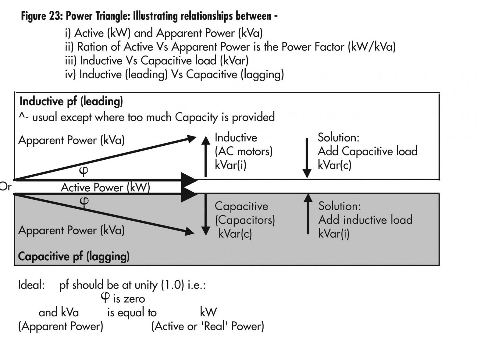
Figure 23: Power Triangle
Figure 23: Power Triangle - Illustrating Relationships Between
- Active (kW) and Apparent Power (kVa)
- Ration of Active Vs Apparent Power is the Power Factor (kW/kVa)
- Inductive Vs Capactive load (kVar)
- Inductive (leading) Vs Capacitive (lagging)
Appendix E: Conversion Factors
| Multiply | By | To Obtain | |
|
Length |
Meters |
3.281 |
Feet |
|
Torque |
Newton-Meters |
0.7376 |
lb-ft |
|
Rotation |
RPM |
6.0 |
Degrees/sec |
|
Moment of Inertia |
Newton-Meters² |
2.42 |
lb-ft² |
|
Power |
Watts |
0.00134 |
HP |
|
Temperature |
Degree C = (Degree F-32) x 5/9 |
||
Page details
- Date modified: