
Ejectors are driven by waste heat or heat from renewable sources, and directly activated by a thermal source to produce heating, cooling or refrigeration. In spite of the apparent geometric simplicity of operating an ejector, predictions of how the system works are very complex because of the hydrodynamic phenomena involved and the process of thermal non-equilibrium. Moreover, since the use of refrigerants in ejectors is recent, there is very little data or information available on their design and operation. The information available is even often contradictory. Consequently, current designs rely on data obtained from air and water. The use of ejectors is therefore limited to a restricted number of applications. Recent efforts to optimize heating and cooling indicate that ejectors have significant potential, but knowledge and operational data must be developed for fluids other than water and air. Knowledge about diphasic ejectors (gas-liquid) is even more limited.

Operation of an ejector
Text version
Ejector
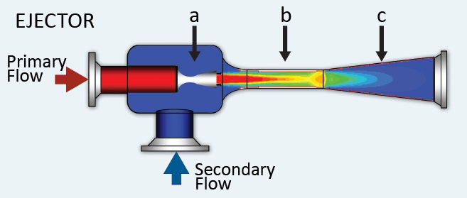
TThe following image represents the operation of an ejector. The ejector diagram is presented in a way that shows us an inside view of the ejector. The body of the ejector consists of a square shape, to which a long nozzle is attached on the right. The part of the nozzle that is attached to the ejector is in the shape of a cylinder while the tip of the nozzle is in the shape of a cone, with its opening being the widest part of the nozzle.
Across from the nozzle, on the left side of the ejector, a red cylinder shape represents the entry of the primary flow. The first half of the cylinder is on the outside of the ejector and the second half is inside. A red arrow points to the cylinder’s opening to represent the entry of the primary flow, coming from the motive fluid. The end of the cylinder, inside the ejector, leads to a small converging-diverging nozzle identified by the letter “a”. It is there that the motive flow is accelerated to reach supersonic speed.
A second cylindrical shape is located at the base of the ejector and represents the entry of the secondary flow, which is the suction fluid from the evaporator. A blue arrow points to the opening of the cylinder to represent the entry of the secondary flow.
The cylindrical part of the nozzle is identified by the letter “b”. This part of the ejector is the mixing chamber where the two flows come into contact.
The conical opening of the nozzle is identified by the letter “c” and is called the diffuser.
The flow coming out of section “a” is multicoloured, going from red to yellow with shades of green and blue, to represent the flow energy in section “b”, the mixing chamber.
For an overview of this technology, see the brochure entitled Capturing the Value of Thermal Energy: Innovations in Ejector Technology from CanmetENERGY.
CanmetENERGY’s research activities are focused on:
- Simple phase ejector for community heating
- Modeling of a diphasic ejector
- Prototypes for refrigeration and cooling
- Demonstration project
CanmetENERGY is seeking research partnerships with universities and industries that share its interest in improving energy efficiency in buildings and reducing greenhouse gas emissions. To discuss a partnership, contact us.
Simple phase ejector for community heating
The aim of the project is to combine the experimental data obtained on a test bed with the results from the Computational Fluid Dynamics (CFD) analysis in order to generate the technical data necessary for ejector design. Operating conditions will be reproduced at a moderate temperature (-10°C at the source and + 50°C in the wells), a temperature range at which ejectors have significant potential. Experiments aim to quantify performance based on the efficiency of the ejector and condenser pressure and ensure operational stability. The test bed will provide information to validate models (1-D and CFD) and necessary data for operation (temperatures, pressure, flows). The final design of the ejector will use this information to optimize the geometry and choose the refrigerant. Data will first be applied to design a community heating and refrigeration system.
Modeling of a diphasic ejector
Since information on this type of ejector is rare, the first task will be to identify and understand the interaction mechanisms between the phases and their impact on the ejector’s behaviour. By using the existing information, a simulation of static and dynamic phenomena will be performed. This modeling will enable the development of design and analysis tools for operation and control parameters.
Diphasic ejectors will be used to improve the performance of heating, cooling and refrigeration systems. The first demonstration of the use of ejectors will be conducted in arenas. The results of the experiment will then be applied to supermarkets, refrigerated warehouses and general cooling systems.
Prototypes for refrigeration and cooling
From the knowledge acquired, two ejector systems will be developed. The first will integrate an ejector into a refrigeration system. In this application, the ejector is fed by the high pressure energy produced by the compressor. The ejector recovers the energy that would otherwise be lost in the expansion valve. The second prototype will use the heat lost to activate an ejector and increase the cooling capacity of the system. In both cases, the prototypes demonstrate the efficiency gains in commercial and industrial conditions.
Demonstration project
In order to transfer the technology from the laboratory to the industry, a demonstration project will be conducted. This project will involve a manufacturer and will target an application that rejects heat from a community heating system. The rejected heat will help to increase the cooling capacity of the system.
Managed by CanmetENERGY at the Varennes (Quebec) research centre.