
Basics of SAR Polarimetry
- Introduction to EM waves and their properties
- Polarimetric scattering
- Polarization in radar systems
- The scattering matrix
- The polarization ellipse
- The polarization state
Introduction to EM waves and their properties
An electromagnetic (EM) plane wave has time-varying Electric and Magnetic Field components in a plane perpendicular to the direction of travel![]() . The two fields are orthogonal to one another, and are described by Maxwell's equations
. The two fields are orthogonal to one another, and are described by Maxwell's equations ![]() . The fields propagate at the speed of light in "free space", which includes most realistic atmospheric conditions. Three parameters are necessary and sufficient to describe the propagation of EM waves in a given medium: dielectric constant (or permittivity), permeability and conductivity.
. The fields propagate at the speed of light in "free space", which includes most realistic atmospheric conditions. Three parameters are necessary and sufficient to describe the propagation of EM waves in a given medium: dielectric constant (or permittivity), permeability and conductivity.
In general, when an EM wave is emitted from a source, such as a radar antenna, it propagates in all available directions, (with a specific field strength and phase in each direction). At a long distance from the antenna, we can assume that the wavefront lies on a plane, rather than on the surface of a sphere. Since we are only interested in what happens to the wave along one specific direction, the "plane wave" assumption is appropriate.
 Did you Know?
The predictable component of the EM wave has a characteristic geometric structure, which defines its polarization properties. When viewed along its direction of propagation, and assuming horizontal and vertical axes with respect to a specific coordinate system (e.g. axes defined parallel to the long and short sides of the radar antenna), the tip of the Electric Field vector traces out a regular pattern. The length of the vector represents the amplitude of the wave, and the rotation rate of the vector represents the frequency of the wave. Polarization refers to the orientation and shape of the pattern traced by the tip of the vector, as discussed in the next section.
Polarization is an important property of a plane EM wave. Polarization refers to the alignment and regularity of the Electric and Magnetic Field components of the wave, in a plane perpendicular to the direction of propagation. By convention, we direct our attention to the Electric Field component of the wave, as the orthogonal Magnetic Field component "follows" it according to Maxwell's equations (the Magnetic Field is directly related to the Electric Field, and can always be calculated from it). For this reason, the EM wave can be characterized by the behaviour of the Electric Field vector as a function of time. The propagation of an electromagnetic wave is illustrated in Figure 1-1.
The waveform of the Electric Field vector can be predictable or random, or a combination of both. A random component is like pure noise, with neither a recognizable frequency nor a pattern to its amplitude. An example of a predictable component is a monochromatic sine wave, with a constant, single frequency and a constant amplitude. An EM wave that has no random component is called fully polarized.
Polarimetric scattering
Having defined how to represent a polarized wave, we now describe how an EM wave of a certain polarization is scattered by a target. In this regard, we will use "target" to mean either a discrete reflector or a distributed surface.
The scattering properties of a target can be measured by a polarimetric radar, as depicted in Figure 1-10. The radar system illuminates the target with an incident wave (A), and the wave is scattered in all directions by the target (C). The radar system records the part of the scattered wave that is directed back towards the receiving antenna (B). Often the receiving antenna is in the same location as the antenna that transmitted the wave - this is called the monostatic case, and the received energy is referred to as backscatter. By controlling the polarization of the incident wave and measuring the full polarization properties of the backscattered wave, the radar system can be used to learn more about the target than by using a single polarization.
|
|
|
A polarimetric or quadrature polarization radar transmits with two orthogonal polarizations, often linear horizontal (H) and linear vertical (V), and receives the backscattered wave on the same two polarizations. This results in four received channels, i.e. HH, HV, VV and VH, where both the amplitude and relative phase are measured. The measured signals in these four channels represent all the information needed to measure the polarimetric scattering properties of the target - hence the quadrature polarization radar is also called a fully polarimetric radar. In the case of dual polarized radars, some but not the entire target scattering properties can be obtained from the two channels.
Polarization in radar systems
How does a radar system create polarized waves? It uses an antenna that is designed to transmit and receive EM waves of a specific polarization. Antennas come in many forms, including horns, waveguides, dipoles and patches. In each case, the electric and mechanical properties of the antenna are such that the transmitted wave is almost purely polarized with a specific design polarization. In a simple radar system, the same antenna is often configured so that it is matched to the same polarization on reception (when an EM wave is incident upon it) ![]() .
.
Signals with components in two orthogonal or basis polarizations are needed to create a wave with an arbitrary polarization. The two most common basis polarizations are horizontal linear or H, and vertical linear or V. Circular polarizations are also in use for some applications, e.g. weather radars. Their basis components are denoted by R for Right Hand Circular and L for Left Hand Circular.
In more complex radar systems, the antenna may be designed to transmit and receive waves at more than one polarization. On transmit, waves of different polarizations can be transmitted separately, using a switch to direct energy to the different parts of the antenna in sequence (e.g. the H and V parts). In some cases the two parts can be used together, for example, a circular polarized signal can be transmitted by feeding the H and V parts of the antenna simultaneously, with signals of equal strength and a 90° phase difference (recall Figure 1-3).
Because the scatterer can change the polarization of the scattered wave to be different from the polarization of the incident wave, the radar antenna is often designed to receive the different polarization components of the EM wave simultaneously. For example, the H and V parts of an antenna can receive the two orthogonal components of the incoming wave, and the system electronics keep these two signals separate.
Denoting the transmit and receive polarizations by a pair of symbols, a radar system using H and V linear polarizations can thus have the following channels:
- HH - for horizontal transmit and horizontal receive,(HH)
- VV - for vertical transmit and vertical receive,(VV)
- HV - for horizontal transmit and vertical receive(HV), and
- VH - for vertical transmit and horizontal receive(VH).
The first two of these polarization combinations are referred to as like-polarized, because the transmit and receive polarizations are the same. The last two combinations are referred to as cross-polarized because the transmit and receive polarizations are orthogonal to one another.
A radar system can have different levels of polarization complexity:
- single polarized - HH or VV or HV or VH
- dual polarized - HH and HV, VV and VH, or HH and VV
- four polarizations - HH, VV, HV, and VH
A quadrature polarized (i.e. polarimetric) radar uses these four polarizations, and measures the phase difference between the channels as well as the magnitudes. Some dual polarized radars also measure the phase difference between channels, as this phase plays an important role in polarimetric information extraction.
The scattering matrix
When a horizontally polarized wave is incident upon a target, the backscattered wave can have contributions in both horizontal and vertical polarizations. The same applies to a vertically polarized incident wave. As the horizontal and vertical components form a complete basis set to describe the electromagnetic wave, the backscattering properties of the target can be completely described by a scattering matrix, S,
 (5)
(5)
which describes the transformation of the Electric Field of the incident wave to the Electric Field of the scattered wave (in (1-5), the superscript i refers to the incident wave, and s refers to the scattered wave). Having measured this matrix, the strength and polarization of the scattered wave for an arbitrary polarization of the incident wave can be computed, as any incident wave can be expressed in the [ Ehi , Evi ] basis set.
The four elements of the scattering matrix are complex, and can be obtained from the magnitudes and phases measured by the four channels of a polarimetric radar. A precise calibration procedure is needed to get the elements, but if the calibration were not necessary, the four scattering matrix elements would be directly measured by the corresponding channels of the radar system. The measured scattering properties of the target apply only at that frequency and radar beam angle used in the mission. However, the scattering properties can vary significantly with radar frequency and beam direction (or rotation of the target), so care should be taken to choose these parameters to be representative of the desired operating scenario.
In monostatic radars, the reciprocity property holds for most targets. This property means that Shv = Svh, i.e. the scattering matrix is symmetrical and has only 3 independent elements. Note that as the elements of the scattering matrix are complex, a phase change that may occur during the scattering process can be represented.
Coordinate conventions: The propagation of a plane EM wave is described in a three-dimensional space with the coordinates given by the three axes x, y and z. The z-axis is in the direction of propagation, while the x- and y-axes lie in a plane perpendicular to the direction of propagation, with the (x, y, z) forming a right-hand orthogonal set. In scattering situations, the coordinate space has to be defined for both the incident wave and the scattered wave.
Two conventions have arisen in the literature; the forward scatter alignment (FSA) and the back scatter alignment (BSA. For the FSA, the positive z-axis is in the same direction as the travel of the wave (for both the incident and scattered wave), while in the BSA, the positive z-axis points towards the target for both the incident and scattered wave. Comparing these two cases, the z-axis points in the same direction for the incident wave, but in opposite directions for the scattered wave. For the monostatic radar case, the coordinate systems are the same for the incident and scattered wave in the BSA convention, so the BSA is more commonly used for imaging radars.
Because of the differing convention rules, the scattering matrix takes on a different form in the BSA and FSA conventions. In the BSA convention, the scattering matrix is called the Sinclair matrix, while in the FSA convention, the scattering matrix is called the Jones matrix ![]() , page 278.
, page 278.
Whiz quiz
Question: How does the polarization of a scattered EM wave differ between the FSA and BSA conventions? The answer is...
Whiz quiz - answer
Answer: The BSA convention can be viewed as seeing the EM wave from the opposite direction as in the FSA convention. This has the effect of reversing the apparent direction of rotation of the wave and results in a change of sign of the ellipticity of the wave.
The polarization ellipse
The Electric Field of a plane wave can be described as the vector sum of two orthogonal components, typically horizontal and vertical components. The two components are characterized by their amplitudes and the relative phase between them. When viewed along its direction of propagation, the tip of the Electric Field vector of a fully polarized wave traces out a regular pattern. In its most general form, the pattern is an ellipse, as shown in Figure 1-2.
Figure 1-2: Polarization ellipse showing the orientation angle  and ellipticity
  , which are a function of the semi-major and semi-minor axes, a and b
The ellipse has a semi-major axis of length a, and a semi-minor axis of length b. The angle of the semi-major axis, measured counter-clockwise from the positive horizontal axis, is the "orientation", , of the EM wave, and can take on values between 0° and 180°. The degree to which the ellipse is oval is described by a shape parameter called eccentricity or ellipticity, defined as = arctan(b/a), which can take values between -45° and +45°.
The shape of the ellipse is governed by the magnitudes and relative phase between the horizontal and vertical components of the Electric Field vector. Figure 1-3 illustrates the effect of relative phase between the components, when the magnitudes of the components are equal. When the components are in phase, the polarization is linear (ellipticity = 0), with an orientation of 45°. As the relative phase angle increases to  /2 radians, the orientation remains at 45°, but the ellipticity increases to 45°, representing circular polarization. This sequence is shown in the top row of Figure 1-3 (plus the first entry in the second row), where the phase in increased in steps of /8.
Then as the relative phase increases from /2 to 3/2 radians, the orientation flips to 135°, and the ellipticity goes from 45° to zero then to -45°. This sequence is shown in rows 2 and 3 of the figure (plus the first entry in the fourth row). Finally in row 4, the relative phase goes from 3
/2 to 15/8, the orientation flips to +45°, and the ellipticity tends to zero again.
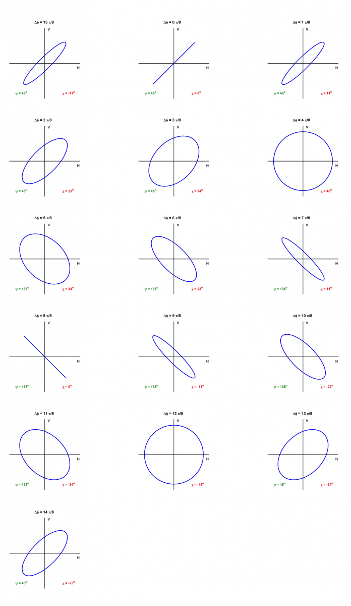
Figure 1-3: The shape of the polarization ellipse as the relative phase between the horizontal and vertical components of the Electric Field vector is varied from 0 to 15 /8 radians in steps of /8
Larger Image
Figure 1-3 illustrates how a circle and a straight line are limiting cases of the ellipse. If the phase angle between the horizontal and vertical components is zero or radians, the ellipse becomes a straight line. In this case, the ellipticity is zero and the polarization is referred to as "linear".
Did you Know?
Did you know that a fully polarized wave could be made up of sine waves of many frequencies? However, in SAR system analysis, we usually assume a single frequency or "monochromatic sine wave". This is a valid assumption, as SAR systems usually have a very narrow bandwidth (compared to the carrier frequency) so that the transmitted wave can be approximated by a sine wave.
Figure 1-3 assumes that the magnitudes of the horizontal and vertical components are equal, but if they are not equal, the orientation can take on any value between 0 and 180°. If the ellipticity is zero and the orientation is = 0 (180° is equivalent), the polarization is horizontal linear (the vertical component is zero), and if = 90°, the polarization is vertical linear (the horizontal component is zero). These are the two linear polarizations in common use.
If the phase angle between the horizontal and vertical components is 90°, and the horizontal and vertical components are equal, the ellipse becomes a circle. In this case, the ellipticity has a magnitude of 45°, and the orientation is not defined. An ellipticity of = +45° corresponds to a left circular polarization and = -45° corresponds to a right circular polarization. If the wave is observed along the direction of propagation, the polarization is left-handed if the rotation of the Electric Field vector is counter-clockwise.
Examples of linear, elliptical and circular polarizations are shown in the figures, where the rotation of the Electric Field vector is also shown.
Whiz quiz

Question: Why are the horizontal and vertical components sufficient to describe the polarization of an EM wave? The answer is...
Whiz quiz - answer
Answer: The polarization of a plane EM wave is described by the locus of its Electric Field vector in a plane perpendicular to the direction of propagation. Two orthogonal components are required to describe the location of the vector in the plane, and horizontal and vertical components, Ex and Ey (or Eh and Ev) are the most convenient ones to use.
The polarization state
The polarization state of a plane wave can be described by orientation and ellipticity, plus a parameter S0 that is proportional to the total intensity of the wave. Writing the horizontal and vertical components of the Electric Field vector as Eh and Ev, the British physicist, Gabriel Stokes, described the polarization state of the EM wave by a 4-element vector, [ S0, Q, U V ] T, now known as the Stokes vector:
 (1)
(1)
where | . | is the absolute value and * is the complex conjugate. An electromagnetic plane wave can be completely polarized, partially polarized or completely unpolarized. In the completely polarized case, only 3 of the Stokes parameters are independent, because of the total power relation:
![]() (2)
(2)
For a completely polarized wave, the polarization state can be described by a point on the Poincaré sphere, as shown in Figure 1-8. The radius of the sphere is S0, the intensity of the wave. The latitude of a point on the sphere corresponds to 2![]() , i.e. two times the ellipticity of the wave.
, i.e. two times the ellipticity of the wave.
Did you Know?
|
 The British physicist, George Gabriel Stokes, was born on August 13, 1819 in Skreen, County Sligo, Ireland, and became a professor at Cambridge in 1849, a position he held until his death on February 1, 1903 (the centennial is soon). In addition to his work with polarimetry and the theory of light, he is also known for his research in fluid mechanics, spectrum analysis, geodesy, and the theory of sound and vector calculus. He was elected as a member of the Royal Society in 1851, and was its president from 1885 to 1890. He was also a member of the British Parliament from 1887 to 1892, noted for supporting educational issues.
The longitude of a point on the sphere corresponds to 2![]() , i.e. two times the orientation of the wave.
, i.e. two times the orientation of the wave.
We can see from this notation that linear polarizations lie on the equator, with horizontal and vertical polarizations opposite each other. Left-hand circular and right-hand circular polarizations lie on the north and south poles respectively. All other points on the sphere represent elliptical polarizations of various ellipticities (![]() ) and orientations (
) and orientations (![]() ). Points on the sphere that are directly opposite one another represent polarizations that are orthogonal to one another, and are referred to as cross polarizations.
). Points on the sphere that are directly opposite one another represent polarizations that are orthogonal to one another, and are referred to as cross polarizations.
If the electromagnetic wave is partially polarized, it can be expressed as the sum of a completely polarized wave and a completely unpolarized or noise-like wave. The degree of polarization is the ratio of the polarized power to the total power, and in terms of the Stokes parameters, the degree of polarization is given by
 (3)
(3)
so that for partially polarized waves, the total power is greater than the polarized power:
![]() (4)
(4)
Figure 1-8: Orientation and ellipticity of a fully polarized wave represented on the Poincaré sphere.
Whiz quiz
Question: If an EM wave is horizontally polarized, what is the corresponding orthogonal polarization? The answer is...
Whiz quiz - answer
Answer: The orthogonal or cross polarization to linear horizontal is linear vertical polarization. Two orthogonal polarizations can form a basis set, used to describe the polarization of an EM wave. Linear horizontal and linear vertical are two orthogonal polarizations that are commonly used as the basis set, but left-hand circular and right-hand circular are sometimes chosen as basis set.
Page details
- Date modified: