
Radar Polarimetry
Introduction to Polarization
When discussing microwave energy propagation and scattering, the polarization of the radiation is an important property. For a plane electromagnetic (EM) wave, polarization refers to the locus of the electric field vector in the plane perpendicular to the direction of propagation. While the length of the vector represents the amplitude of the wave, and the rotation rate of the vector represents the frequency of the wave, polarization refers to the orientation and shape of the pattern traced by the tip of the vector.
The waveform of the electric field strength (voltage) of an EM wave can be predictable (the wave is polarized) or random (the wave is unpolarized), or a combination of both. In the latter case, the degree of polarization describes the ratio of polarized power to total power of the wave. An example of a fully polarized wave would be a monochromatic sine wave, with a single, constant frequency and stable amplitude.
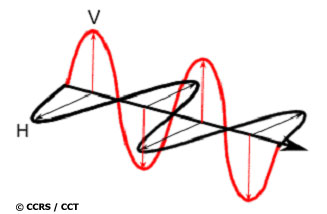
Examples of horizontal (black) and vertical (red) polarizations of a plane electromagnetic wave
Many radars are designed to transmit microwave radiation that is either horizontally polarized (H) or vertically polarized (V). A transmitted wave of either polarization can generate a backscattered wave with a variety of polarizations. It is the analysis of these transmit and receive polarization combinations that constitutes the science of radar polarimetry.
Any polarization on either transmission or reception can be synthesized by using H and V components with a well-defined relationship between them. For this reason, systems that transmit and receive both of these linear polarizations are commonly used. With these radars, there can be four combinations of transmit and receive polarizations:
- HH - for horizontal transmit and horizontal receive
- VV - for vertical transmit and vertical receive
- HV - for horizontal transmit and vertical receive, and
- VH - for vertical transmit and horizontal receive.
The first two polarization combinations are referred to as "like-polarized" because the transmit and receive polarizations are the same. The last two combinations are referred to as "cross-polarized" because the transmit and receive polarizations are orthogonal to one another.
Radar systems can have one, two or all four of these transmit/receive polarization combinations. Examples include the following types of radar systems:
| single polarized | - HH or VV (or possibly HV or VH) |
|---|---|
| dual polarized | - HH and HV, VV and VH, or HH and VV |
| alternating polarization | - HH and HV, alternating with VV and VH |
| polarimetric | - HH, VV, HV, and VH |
Note that "quadrature polarization" and "fully polarimetric" can be used as synonyms for "polarimetric". The relative phase between channels is measured in a polarimetric radar, and is a very important component of the measurement. In the other radar types, relative phase may or may not be measured. The alternating polarization mode has been introduced on ENVISAT - relative phase is measured but the important HH-VV phase is not meaningful because of the time lapse between the measurements.
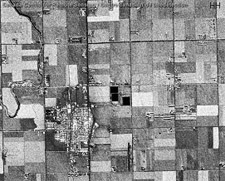
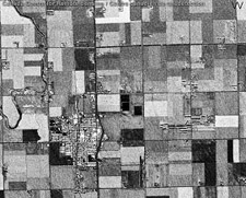
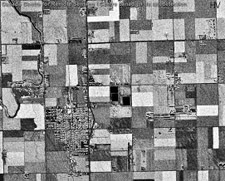
These C-band images of agricultural fields demonstrate the dependence of the radar response on polarization. The top two images are like-polarized (HH on left, VV on right), and the lower left image is cross-polarized (HV). The lower right image is the result of displaying these three images as a colour composite (in this case, HH - red, VV - green, and HV - blue).
Both wavelength and polarization affect how a radar system "sees" the elements in the scene. Therefore, radar imagery collected using different polarization and wavelength combinations may provide different and complementary information. Furthermore, when three polarizations are combined in a colour composite, the information is presented in a way that an image interpreter can infer more information of the surface characteristics.
 |
 |
 |
 |
Illustration of how different polarizations (HH, VV, HV & colour composite) bring out different features in an agricultural scene
Polarimetric Information
The primary description of how a radar target or surface feature scatters EM energy is given by the scattering matrix. From the scattering matrix, other forms of polarimetric information can be derived, such as synthesized images and polarization signatures.
Polarization Synthesis
A polarimetric radar can be used to determine the target response or scattering matrix using two orthogonal polarizations, typically linear H and linear V on each of transmit and receive. If a scattering matrix is known, the response of the target to any combination of incident and received polarizations can be computed. This is referred to as polarization synthesis, and illustrates the power and flexibility of a fully polarimetric radar.
Through polarization synthesis, an image can be created to improve the detectability of selected features. An example is the detection of ships in ocean images. To find the best transmit-receive polarization combination to use, the polarization signature of a typical ship and that of the ocean is calculated for a number of polarizations. Then the ratio of the ship to ocean backscatter is computed for each polarization. The transmit-receive polarization combination that maximises the ratio of backscatter strength is then used to improve the detectability of ships. This procedure is called "polarimetric contrast enhancement" or the use of a "polarimetric matched filter".
Polarization Signatures
Because the incident and scattered waves can take on so many different polarizations, and the scattering matrix consists of four complex numbers, it is helpful to simplify the interpretation of the scattering behaviour using three-dimensional plots. The "polarization signature" of the target provides a convenient way of visualising a target's scattering properties. The signatures are also called "polarization response plots".
An incident electromagnetic wave can be selected to have an electric field with ellipticity between -45º and +45º, and an orientation between 0 and 180º. These variables are used as the x- and y-axes of a 3-D plot portraying the polarization signature. For each of these possible incident polarizations, the strength of the backscatter can be computed for the same polarization on transmit and receive (the co-polarized signature) and for orthogonal polarizations on transmit and receive (the cross-polarized signature). The strength is displayed on the z-axis of the signatures.
| Co-polarized signature | Cross-polarized signature |
|---|---|
 |
 |
Polarization signatures of a large conducting sphere.
P = Power, O = Orientation (degrees), E = Ellipticity (degrees)
This figure shows the polarization signatures of the most simple of all targets - a large conducting sphere or a trihedral corner reflector. The wave is backscattered with the same polarization, except for a change of sign of the ellipticity (or in the case of linear polarization, a change of the phase angle between Eh and Ev of 180o). The sign changes once for every reflection - the sphere represents a single reflection, and the trihedral gives three reflections, so each behaves as an "odd-bounce" reflector.
For more complicated targets, the polarization signature takes on different shapes. Two interesting signatures come from a dihedral corner reflector and Bragg scattering from the sea surface. In the case of the dihedral reflector, the co-pol signature has a double peak, characteristic of "even-bounce" reflectors. In the case of Bragg scattering, the response is similar to the single-bounce sphere, except that the backscatter of the vertical polarization is higher than that of the horizontal polarization.
Data Calibration
One critical requirement of polarimetric radar systems is the need for calibration. This is because much of the information lies in the ratios of amplitudes and the differences in phase angle between the four transmit-receive polarization combinations. If the calibration is not sufficiently accurate, the scattering mechanisms will be misinterpreted and the advantages of using polarization will not be realised.
Calibration is achieved by a combination of radar system design and data analysis. Imagine the response to a trihedral corner reflector. Its ideal response is only obtained if the four channels of the radar system all have the same gain, system-dependent phase differences between channels are absent, and there is no energy leakage from one channel to another.
In terms of the radar system design, the channel gains and phases should be as carefully matched as possible. In the case of the phase balance, this means that the signal path lengths should be effectively the same in all channels. Calibration signals are often built into the design to help verify these channel balances.
In terms of data analysis, channel balances, cross-talk and noise effects can be measured and corrected by analysing the received data. In addition to analysing the response of internal calibration signals, the signals from known targets such as corner reflectors, active transponders, and uniform clutter can be used to calibrate some of the parameters.
Polarimetric Applications
Synthetic Aperture Radar polarimetry has been limited to a number of experimental airborne SAR systems and the SIR-C (shuttle) mission. With these data, researchers have studied a number of applications, and have shown that the interpretation of a number of features in a scene is facilitated when the radar is operated in polarimetric mode. The launch of RADARSAT-2 will make polarimetric data available on an operational basis, and uses of such data will become more routine and more sophisticated.
Some applications in which polarimetric SAR has already proved useful include:
- Agriculture: for crop type identification, crop condition monitoring, soil moisture measurement, and soil tillage and crop residue identification;
- Forestry: for clearcuts and linear features mapping, biomass estimation, species identification and fire scar mapping;
- Geology: for geological mapping;
- Hydrology: for monitoring wetlands and snow cover;
- Oceanography: for sea ice identification, coastal windfield measurement, and wave slope measurement;
- Shipping: for ship detection and classification;
- Coastal Zone: for shoreline detection, substrate mapping, slick detection and general vegetation mapping.
Did you know?
That many other polarizations can be transmitted (or received) if a radar system can transmit or receive the H and V channels simultaneously. For example, if a radar system transmits an H and a V signal simultaneously, and the V signal is 90o out of phase with respect to the H signal, the resulting transmitted wave will have circular polarization.
Whiz quiz
Can sound waves be polarized?
The answer is ...
Whiz quiz - answer
Polarization is a phenomenon which is characteristic of those waves that vibrate in a direction perpendicular to their direction of propagation. While electromagnetic waves vibrate up/down, side to side and in intermediate directions, sound waves vibrate in the same direction as their direction of travel, so cannot be polarized.
Page details
- Date modified: