ARCHIVED - Energy Efficiency in Buildings
Information Archived on the Web
Information identified as archived on the Web is for reference, research or recordkeeping purposes. It has not been altered or updated after the date of archiving. Web pages that are archived on the Web are not subject to the Government of Canada Web Standards. As per the Communications Policy of the Government of Canada, you can request alternate formats. Please "contact us" to request a format other than those available.
Use of Variable Frequency Drives for Fan and Pump Control
Description

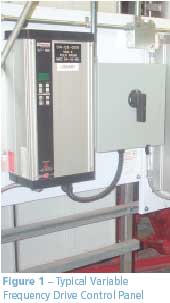
In the past 10 years, variable speed control for fans, pumps, chillers and HVAC systems has become an affordable way to save energy, thanks to advances in microelectronics and control technology. Initially, utility companies introduced incentives to make it practical to switch from fixed speed and flow-throttling controls to variable frequency drives (VFDs) (Figure 1). Since then, more building designs have been specifying VFDs, and many building HVAC retrofits can become more cost-effective by replacing flow controls with VFDs at installed costs as low as $250 per kilowatt. Naturally, the process must be carefully studied to ensure that the application will be successful.
Technical Specifications
Drive Specification – VFDs operate by converting the incoming AC power to a DC signal and then re-transmitting the power signal to the motor at varying frequencies and voltages. VFDs can operate rotating equipment at speeds ranging from nearly 0 RPM to as high as 150 percent of the rated speed for the motor. The use of a frequency drive requires installing high-efficiency Class F insulated motors that can withstand the variations in voltage and current flux.
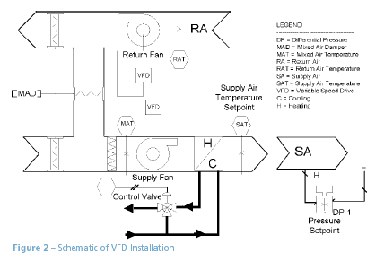
Applications – Some good applications include 1) replacing outlet dampers or variable inlet vanes (VIVs) in supply fan systems controlling variable air volume (VAV) boxes; 2) controlling air supply to multiple zones by adding a VFD and isolation dampers in zones with different occupancy and operating schedules; and 3) controlling pump speed by maintaining a pressure setpoint. Other advantages of variable frequency drives include less wear on the motor due to reduced speed and torque, gentler starting through gradual acceleration, and fewer moving parts (i.e., no damper or inlet vanes to wear out). Figure 2 shows a typical fan application requiring two VFDs with pressure control feedback.
Energy Information
The real energy savings from variable frequency drives come from the basic laws of fan and pump operation. Theoretically, fan power input will drop according to the cube of the flow rate (load). This is illustrated in the equation below:
W2=W1×(Q2/Q1)3

As an example, if the Power (W1) is at 100 percent flow (Q1) and the flow is reduced to 80 percent, the new Power (W2) will be
W1 × (0.8)3 = 0.51 or 51 percent.
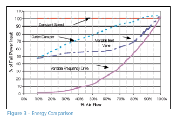
When a fan is throttled back by an inlet vane, the power drops along with the flow rate to a certain value. However, the poor inlet or outlet conditions cause fan performance to suffer, motor efficiency drops as the load is removed, and power savings are reduced (Figure 3). In the case of a VFD, the motor and fan speed are reduced and the losses are much smaller, approaching that of the ideal case.
Comparison
Figure 3 illustrates the difference in power consumption of a typical VFD compared to three common retrofit applications, including VIV control, outlet damper control and constant speed. To estimate the energy savings from a VFD installation, the duty cycle of the equipment must be established. For example, if a fan system was off for eight hours per day, and operated for eight hours at 50 percent flow, six hours at 80 percent flow and two hours at 100 percent flow, the power saving from VFD control would be 40 percent over an inlet vane and 55 percent over outlet damper control.

Case Study
In 1997, a Bank of Montreal building in Vancouver, British Columbia, retrofitted its HVAC systems as part of a building upgrade. The building's previous main air system consisted of a 75-hp supply fan and a 40-hp return fan, which provided air for variable and constant volume mixing, and heating boxes that provided heating and cooling to various zones. The fan was fitted with VIVs, which modulated to maintain the pressure in the system. The retrofit consisted of replacing the fan motors with a 50-hp supply and a 25-hp return, and installing a variable frequency drive in place of the inlet vanes. Based on the 24-hour duty cycle of operation shown in Table 1, the new system saves an estimated $6,294 per year based on 1997 rates, with a simple payback period of three years.
Table 1 – Savings Estimate for Bank of Montreal VFD
| Installation | ||||
| DUTY CYCLE | ||||
| Percent Flow | Hours/Day | |||
| Energy Rate | $0.05/kWh | 0% | 8 | |
| Capital Cost | $18,750 | 60% | 4 | |
| Rated Power | 50+25 hp | 80% | 6 | |
| Operation | 365 days/yr | 100% | 6 | |
| Payback Summary | ||||
|
VFD
|
VIV
|
|||
| Monthly Cost | $1,096 | $1,422 | ||
| Yearly Cost | $10,472 | $16,766 | ||
| Monthly Savings | $517 | |||
| Yearly Savings | $6,294 | |||
| Payback Period (years) | 3.0 | |||
| Return on Investment | 34% | |||
Buildings Division
Office of Energy Efficiency
Natural Resources Canada
580 Booth Street, 18th floor
Ottawa ON K1A 0E4
Tel.: 877-360-5500 (toll free)
Fax: 613-947-4121
Web site
Page details
- Date modified: