
Air Compressor Types and Controls
There are two basic types of air compressors:
- Positive displacement, and
- Dynamic.
Positive Displacement.
In the positive displacement type, a specified quantity of air is trapped in a compression chamber and the volume which it occupies is mechanically reduced, causing a corresponding rise in pressure prior to discharge. Rotary screw, vane and reciprocating air compressors are the three most common types of air positive displacement compressors found in small and medium sized industries.
Dynamic.
Dynamic air compressors include centrifugal and axial machines, and are used in very large manufacturing facilities. These units are beyond the scope of this document.
a. Rotary Screw Compressors
Rotary screw compressors have gained popularity and market share (compared to reciprocating compressors) since the 1980s. These units are most commonly used in sizes ranging from about 5 to 900 HP. The most common type of rotary compressor is the helical twin, screw compressor. Two mated rotors mesh together, trapping air, and reducing the volume of the air along the rotors. Depending on the air purity requirements, rotary screw compressors are available as lubricated or dry (oil free) types.
Text version
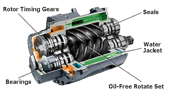
Figure 6 - Cross Section of a Representative Rotary Screw Compressor
cut-away illustration showing rotor timing gears, seals, water jacket, oil-free rotate set, and bearings.
Figure 6 - Cross Section of a Representative Rotary Screw Compressor
The biggest advantage of screw compressors over small air cooled reciprocating units is that they can run at full load continuously where the reciprocating compressors must be used at 60% duty cycle or below. Rotary screws are also a lot quieter and produce cooler air that is easier to dry. Be aware that rotary screw compressors may not be the most efficient choice compared to start/stop reciprocating compressors. Please refer to Case 3: On/Off vs. Load/No Load Control on page 101 for an example.
Lubricant Injected Rotary Screw.
The lubricant injected rotary screw compressor is the dominant type of industrial compressor for a perse set of applications. For lubricant injected rotary screw compressors, lubricants may be a hydrocarbon composition or a synthetic product. Typically a mixture of compressed air and injected lubricant exits the air end and is passed to a sump where the lubricant is removed from the compressed air. Directional and speed changes are used to separate most of the liquid. The remaining aerosols in the compressed air then are separated by means of a separator element within the sump, resulting in a few parts per million (ppm) of lubricant carryover in the compressed air. With two stage compressors, interstage cooling and the reduced internal losses due to a lower pressure across each stage increase the compression efficiency. Consequently, less energy is required to compress the air to the final pressure.
Dry Type Rotary Screw.
In the dry type, the intermeshing rotors do not contact one another, and their relative clearances are maintained to very close tolerances by means of external lubricated timing gears. Most designs use two stages of compression with an intercooler and aftercooler. Lubricant free rotary screw compressors have a range from 25 to 1,200 HP or 90 to 5,200 cfm.
b. Reciprocating Compressors
Reciprocating compressors have a piston that is driven through a crankshaft and by an electric motor. Reciprocating compressors for general purpose use are commercially obtainable in sizes from less than 1 HP to about 30 HP. Reciprocating compressors are often used to supply air to building control and automation systems.
Large reciprocating compressors still exist in industry, but they are now no longer commercially available, except for use in specialized processes such as high pressure applications.
c. Vane Compressors
A rotary vane compressor uses an elliptical slotted rotor situated within a cylinder. The rotor has slots along its length, each slot contains a vane. The vanes are forced outwards by centrifugal force when the compressor is rotating, and the vanes move in and out of the slot because the rotor is eccentric to the casing. The vanes sweep the cylinder, sucking air in on one side and ejecting it on the other. In general, vane compressors are used for smaller applications where floor space is an issue; however, they are not as efficient as rotary screw compressors.
d. Compressor Motors
Electric motors are widely used to provide the power to drive compressors. As a prime mover, the motor needs to supply sufficient power to start the compressor, accelerate it to full speed, and keep the unit operating under various design conditions. Most air compressors use standard, three phase induction motors.
For new or replacement air compressors, premium high efficiency motor should be specified over a standard ones. The incremental cost of the premium high efficiency motor is usually recovered quickly from the consequential energy savings.
For additional information about energy efficient motors, please refer to the Electric Motors Energy Efficiency Reference Guide published by CEATI.
e. Compressor Controls and System Performance
As air systems seldom operate at full load all of the time, the ability to efficiently control flow at part loads is essential.
Consideration should be placed to both compressor AND system control selection as they are important factors affecting system performance and energy efficiency.
Various inpidual compressor control strategies exist including the following:
- Start/Stop. This is the simplest and most efficient control strategy. It can be applied to either reciprocating or rotary screw compressors. Essentially, the motor driving the compressor is turned on or off in response to the discharge pressure of the machine. For this strategy, a pressure switch provides the motor start/stop signal. Start/Stop strategies are generally appropriate for compressors smaller than 30 horsepower in size.
Repeated starts may cause the motor to overheat and place greater maintenance demands on compressor components. For this reason, care should be taken in sizing storage receivers and maintaining wide working pressure bands to keep motor starts within allowable limits.
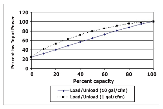
- Load/Unload. This control mode is sometimes called online/offline control. It keeps the motor running continuously, but unloads the compressor when the discharge pressure is adequate. Unloaded rotary screw compressors typically consume 15-35% of their full load power demand, while producing no useful compressed air output. Optional unload timers are available that will save energy by automatically turning off the compressor and placing it in standby if the unit runs unloaded for a period of time (usually 15 minutes).
Load/unload control strategies require significant control storage receiver capacity for efficient part load operation.
Text version
| Percent kw Input Power | Percent capacity (Load/unload 1 gal/cfm) | Percent capacity (Load/unload 10 gal/cfm) |
|---|---|---|
| 0% | 25% | 25% |
| 20% | 55% | 40% |
| 40% | 70% | 58% |
| 60% | 85% | 75% |
| 80% | 95% | 90% |
| 100% | 100% | 100% |
Figure 7 - Average Power vs. Capacity for Rotary Screw Compressor
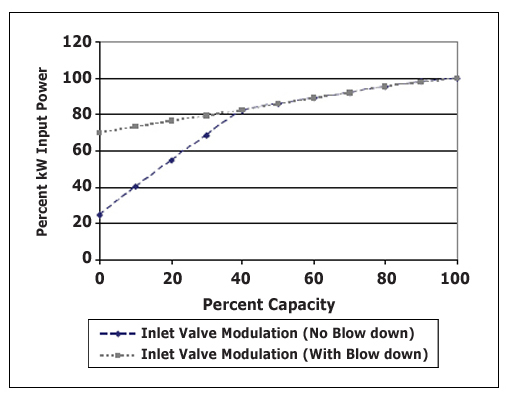
- Modulating Control. This mode of control varies the compressor output to meet flow requirements by adjusting the inlet valve, resulting in air restrictions to the compressor. Even fully modulated at zero flow rotary screw compressors typically consume about 70% of their full load power demand. The use of pressure switch activated unloading controls can reduce the unloaded power consumption to 15 to 35%. Modulating control is unique to lubricated screw compressors and is the least efficient way to operate these units.
Compressor controls have a significant impact on energy consumption, especially at lower flows, where start/stop controls are generally the most energy efficient.
Figure 8 illustrates a typical performance curves for compressors where inlet valve modulation is used with and without unloading the compressor.
Text version
| Percent kw Input Power | Percent capacity (Inlet valve modulation - no blow down) | Percent capacity (Inlet valve modulation - with blow down) |
|---|---|---|
| 0% | 25% | 70% |
| 20% | 55% | 75% |
| 40% | 82% | 82% |
| 60% | 90% | 90% |
| 80% | 95% | 95% |
| 100% | 100% | 100% |
Figure 8 - Rotary Screw Compressor with Inlet Modulation Control
- Variable Displacement.
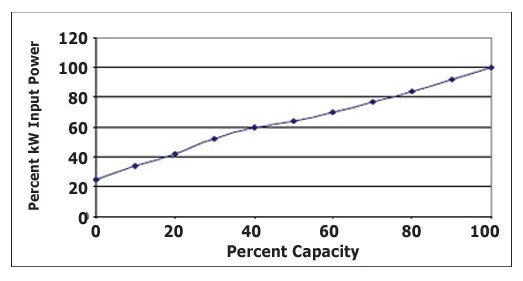
Some lubricated rotary screw compressors vary their output capacity using special capacity control valves, also called spiral, turn or poppet valves. With a variable displacement control scheme, the output pressure and compressor power consumption can be closely controlled without having to start/stop or load/unload the compressor. This control method has good efficiency at points above 60% loading. Use of pressure switch activated unloading controls at flows below 40% capacity can significantly reduce power consumption at lower flows.
Text version
| Percent kw Input Power | Percent capacity |
|---|---|
| 0% | 25% |
| 20% | 40% |
| 40% | 60% |
| 60% | 70% |
| 80% | 80% |
| 100% | 100% |
Figure 9 - Rotary Screw Compressor with Variable Displacement
(Courtesy Compressed Air Challenge)
- Variable Speed Drive (VSD).
This control method varies the speed of the compressor to respond to changes in air demand. Both lubricated and oil free screw compressors can be purchased equipped with variable speed drive controls that continuously adjust the drive motor speed to match the variable demand requirements and maintain constant pressure. These compressors usually operate in on/off or load/unload control when air loading drops below the minimum speed of the drive.
In most cases a variable speed drive compressors offers the most efficient part load operation. Ideally, when there are multiple air compressors at a facility. One or more fixed speed compressors would supply the base load compressed air, and a VSD compressor would be used to supply the fluctuating or trim load.
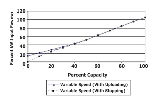
Text version
| Percent kw Input Power | Percent capacity (variable speed - with uploading) | Percent capacity (variable speed - with stopping) |
|---|---|---|
| 0% | 15% | 0% |
| 20% | 30% | 25% |
| 40% | 42% | 42% |
| 60% | 60% | 60% |
| 80% | 85% | 85% |
| 100% | 105% | 105% |
Figure 10 - Variable Speed Rotary Screw Power Curve
To benefit from VSD compressors, the appropriate amount of air receiver storage volume needs to be evaluated for different flow and control scenarios.
Variable speed drive (VSD) compressors should be considered for trim (or swing) duty as they are typically the most efficient unit to supply partial loads. Capable of supplying a constant pressure through a wide control range, the energy consumption and flow of a VSD compressor is almost directly proportional to the speed. This can result in energy savings over comparable fixed speed units when compressors are partially loaded. Be aware, however, that at full loads, the VSD will use slightly more energy compared to a similar sized constant speed motor drive.
Operating Cost Comparison of Different Control Modes
The compressor control mode can have a big effect on operating costs. In modulating mode the compressor would use 90% of full load power. For load/unload with minimal air storage (1 US Gal per cfm), the compressor would use about 92% of full power. By increasing the air storage to 10 US Gal per cfm, the load/unload compressor will use about 77% of full power. With variable speed drive control, the same size compressor will use about 66% of full power.
| % Load | Modulating | Load/Unload with 1 gal/cfm Receiver |
Load/Unload with 10 gal/cfm Receiver |
Variable Speed Drive |
|---|---|---|---|---|
| 100 | $36,130 | $36,130 | $36,130 | $36,850 |
| 75 | $33,420 | $34,680 | $29,350 | $27,090 |
| 65 | $32,330 | $33,240 | $27,820 | $23,480 |
| 50 | $30,710 | $31,070 | $24,200 | $18,060 |
| 25 | $28,000 | $24,930 | $16,800 | $9,030 |
| 10 | $26,370 | $16,620 | $11,740 | $3,610 |
*Based on 10 cents per kWh and 4,250 hours per year.
f. Multiple Compressor System Controls
The goal in controlling multiple compressors is to automatically maintain the lowest and most constant pressure, through all flow conditions, while ensuring all running compressors except one are either running at full load or off. The remaining compressor (trim unit) should be the one most capable of running efficiently at partial loads.
Local compressor controls independently balance the compressor output with the system demand and are always included in the compressor package. To achieve the stated goals, systems with multiple compressors require more advanced controls or control strategies (cascaded pressure bands, network or system master controls) to coordinate compressor operation and air delivery to the system.
Proper coordination is required to maintain adequate system pressures and increased efficiency whenever more than one compressor is required to run in a compressed air system.
Because compressor systems are generally sized to meet a facility’s maximum demand, but are normally running at partial loads, a method of control is required to ensure the running compressors are at their maximum efficiency. A description of some common control methods follows:
- Cascaded Pressure Band Control. This type of control is the simplest method of coordinating multiple compressors. With this control strategy the local compressor pressure switch controls are arranged in an overlapping or cascaded pattern (see Figure 12). This method of control will unload and/or load compressors at varying system pressures as the load decreases or increases. The cascaded control method results in higher than necessary system pressures during partial loads which causes higher than required energy consumption. Also, as the number of coordinated compressors increases, it becomes more and more difficult to achieve accurate compressor control without exceeding the pressure rating of the connected compressors at low loads or experiencing low system pressure at high loads.
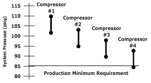
Text version
Figure 12 - Multiple Compressor Cascading Control;
compressor #1 operates with a system pressure (psig) of 100 to 110 psig;
compressor #2 operates with a system pressure (psig) of 95 to 105 psig;
compressor #1 operates with a system pressure (psig) of 90 to 100 psig;
compressor #1 operates with a system pressure (psig) of 85 to 95 psig;Figure 12 - Multiple Compressor Cascading Control
- Network Control. This type of control uses the optional feature of the local compressor control to communicate with other compressors to form a chain of communication that makes decisions to stop/start, load/unload, modulate, and vary speed. One compressor generally assumes the primary lead with the others being secondary to the instructions from this compressor. This type of control can accommodate many compressors while maintaining system pressure within a single lower pressure band for all flow conditions. Typically these types of controls can only interconnect compressors of the same manufacturer.
- System Master Controls. (Also called automatic sequencers). Similar to network controls these externally installed controls interface with the local compressor controller to ensure system pressure remains within a single more efficient lower pressure band. Most system master controls can accommodate different manufacturers and types of compressors in the same system. Some newer system master controls have many extra capabilities, including the ability to monitor and control important parameters in the system.
- Multiple Controls with Variable Speed Drives (VSD). One or more VSD compressor(s) can be incorporated in the compressor control strategies previously indicated. In doing so it is important to ensure that the variable capacity is equal to or larger than the largest fixed speed compressor or a control gap will result. A control gap is where, under certain conditions, neither the base capacity nor the VSD will satisfy system loading. This control gap will cause the base and VSD compressors to fight for lead position and will lower system efficiency. Your compressor provider can assist you with properly sizing your VSD compressors.
To benefit from multiple compressor control, the appropriate amount of air receiver storage volume needs to be installed to slow system pressure changes and allow time to start and stop compressors. Storage is most important for load/unload control but is also required for systems using VSD compressors.
Previous | Table of Contents | Next
Page details
- Date modified: